

The National Institute of Certified Floor-Covering Inspectors (NICFI) is a
non-profit association of independent floor covering inspectors. NICFI members are expert flooring failure analysts and expert witnesses in flooring problems and failures.
NICFI members are experienced in the inspection and failure analysis of
woven carpet, broadloom carpet, resilient tile, rubber tile, cork tile, ceramic tile, resilient sheet vinyl, vinyl composition tile, LVT, hardwood, laminate, solid vinyl,
and specialty flooring materials.
NICFI members attend the annual NICFI Convention in Dalton, Georgia, to increase their knowledge and update their skills. The Annual Convention includes updates on indicative field testing
procedures, tools, products and product defects. The NICFI is the only Non-Profit Association in the Flooring Industry with membership comprised solely of Certified Floor Covering Inspectors.


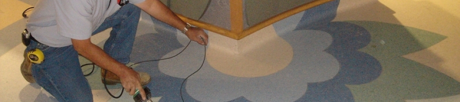
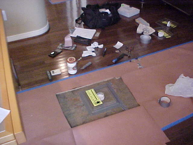
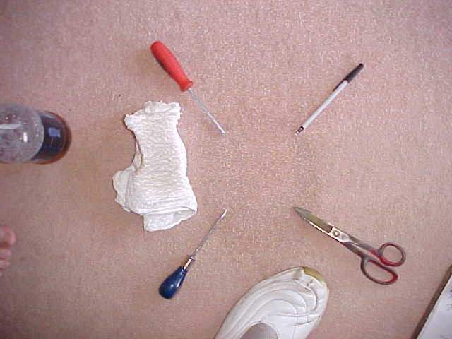
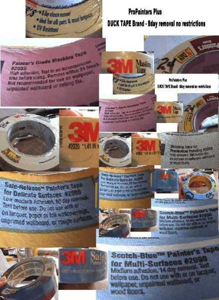
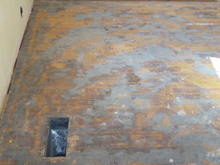
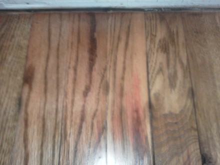
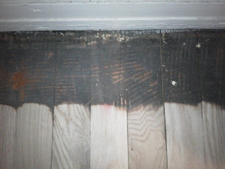
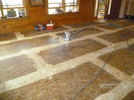
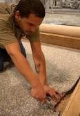
PHOTOS
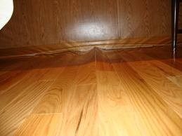
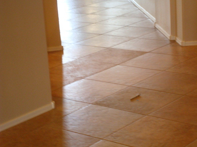
IS THIS YOUR COMPLAINT?


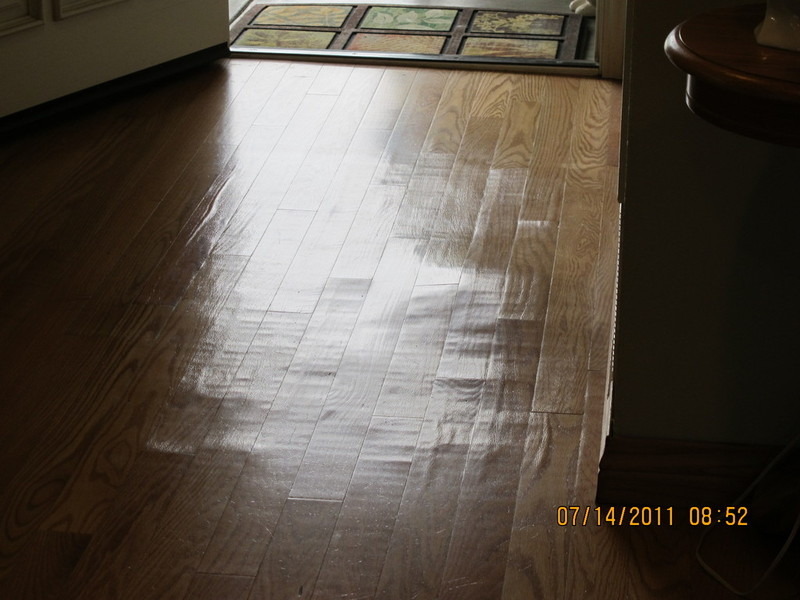


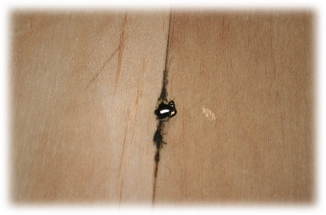


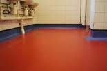
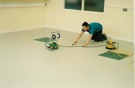
SHEET VINYL
CONTENTS BELOW INCLUDE:
- MOISTURE PROBLEMS #1
- HEAT WELDED INTERGRATED COVE
- INTERGRATED COVE CHEMICAL WELD
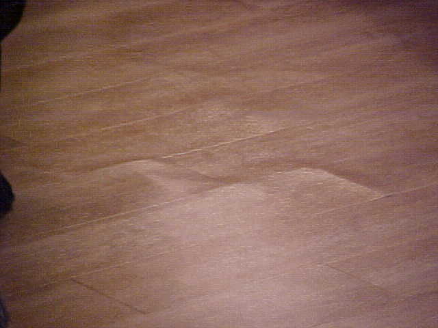
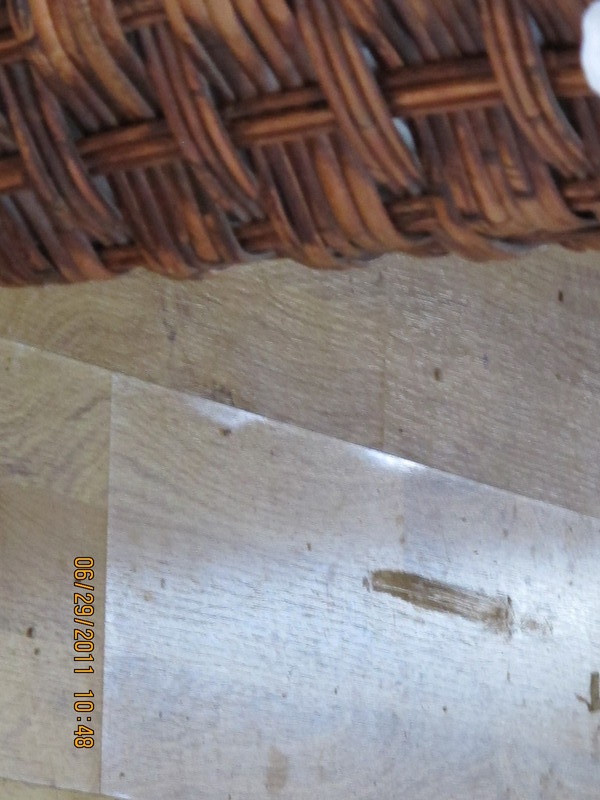
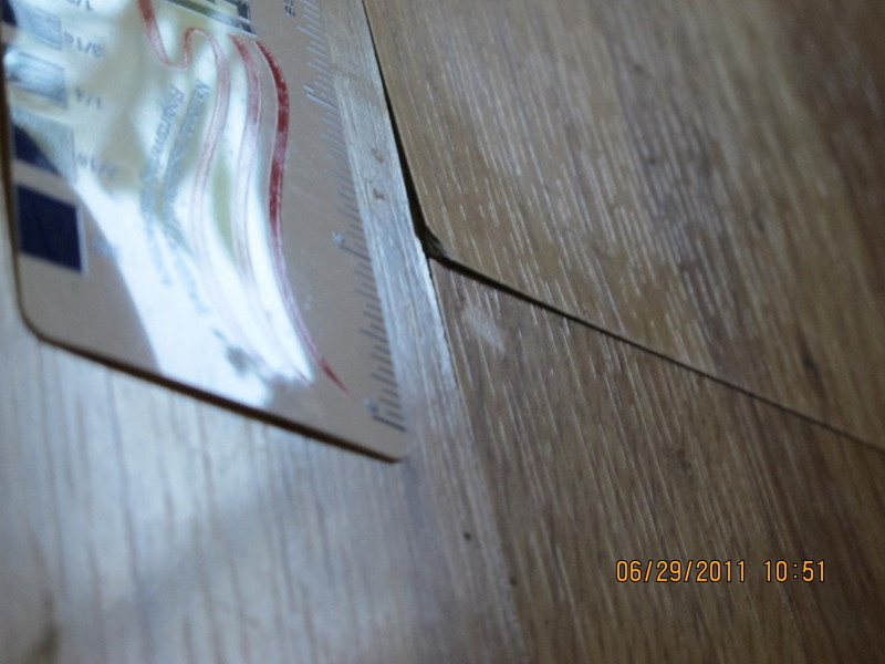
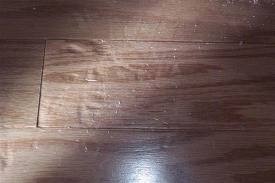
- 30 KNOWN CAUSES OF JOINT (SEAM) TELEGRAPHING
MPEG video file [77.5 MB]
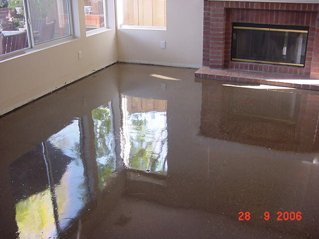
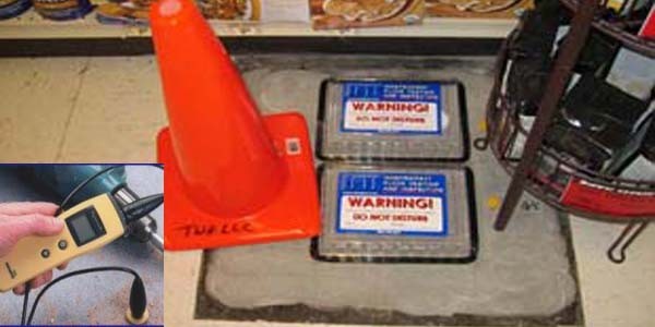
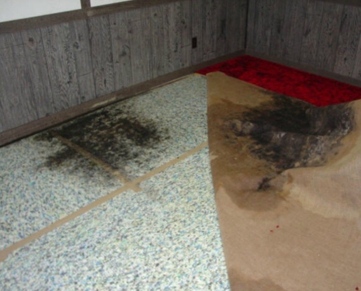
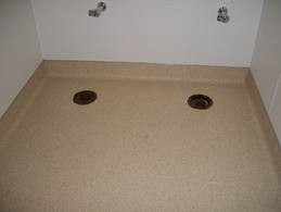
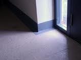
1. MOISTURE PROBLEMS THE VINYL FLOOR COVERING ENEMY #1

HOW TO DEFEAT MOISTURE PROBLEMS, FLOOR COVERING ENEMY NUMBER ONE
BertYanceyJMFCo. ConSeal
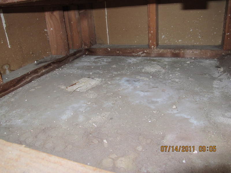
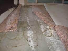
Porous by nature, concrete absorbs moisture from outside sources and moves it upward by way of interconnecting pores created during the curing process. This upward movement of moisture through concrete has been a continuing source of major problems for the floor covering industry,
typically resulting in staining, efflorescence, mildew, separation of adhesive and the floor covering from the slab. Historically, solutions have been very expensive and/or labor intensive. Hot tar and felt, cold stick products, sheet vinyl membranes and epoxy paints and coatings of various
types have all been used with some degree of success, but none seem to be truly effective when moisture and hydrostatic pressure are constantly present in the slab. The main reason is that they are top coatings. Thus, they adhere to the surface of the concrete and are subject to moisture and pressure from below. This causes them to separate from the concrete, just like the floor coverings they are supposed to protect. Modern technology has developed an effective method of moisture protection. It's a water based penetrating treatment for concrete applied quickly and easily with a paint roller or sprayer that is absorbed into the concrete. The process impregnates the pores with a gel, forming a moisture barrier
within the concrete, rather than on the surface. It is effective below as well as on grade and is compatible with all types of mastics, adhesives and floor coverings.
Howard PriestDependable Chemical Co.
The moisture problems not generally addressed or understood by our industry are self-induced problems. For example, the underlayment board might not have waterproof glue in the laminates which can cause swelling when moisture is drawn into the joints or raw surface areas from the fluid in the patch or adhesive.To avoid this, stir together equal parts of alcohol and clear shellac in a clean container. Then brush coat the joints, hammer head indents and sanded or planed surface areas before patching or spreading adhesive. A sort of reverse moisture problem can occur if you don't allow the patch to dry completely before applying adhesive. What happens is that some of the adhesive is drawn into the damp patch causing a poor bond of vinyl to the floor. This points up the need for installers to allow enough time for the patch to thoroughly dry before applying adhesives. A misunderstood moisture is mildew. Floor patch gets most of the blame for causing mildew, when in fact, most stains or discolorations are actually not related to either the patch or adhesive.
Roger SalamonMidland Corp.
Successful installations are the result of careful initial planning and use of proper materials. Every care must be taken to anticipate those unexpected moisture problems which cause a job to fail. One important approach to controlling moisture is by the use of a latex floor/wall primer.
Consider the facts — it dries quickly, has no offensive odors or hazardous fumes and easily cleans up with water. There are three situations that require the inclusion of the primer. First, on new or dusty concrete, the primer forms a surface film, penetrates the surface pores and provides a solid bonding surface for the subsequent application of adhesive. This is especially important where self-stick tile is installed. As for dust, the primer ties it down permanently, forming a rigid bondable surface which is capable of accepting a permanent covering. Secondly, when applied to plywood sub-surfaces, the primer prevents adhesive migration from the tile to the plywood surface. Most self-stick tile failures, whether vinyl or wood, can be averted by priming. The same applies to sheet goods installed on plywood in areas adjacent to hot air registers and near exit/entrance doors. Finally, on new dry wall surfaces over which mastic is to be applied, primer will prevent the dry wall surface from absorbing the resins in the mastic which cause the mastic to dry out and the tile to become loose. Priming will also keep unwanted outside moisture from getting in behind the tile, protecting the adhesive bond as well as the wall itself.
Robert DempseyCongoleum
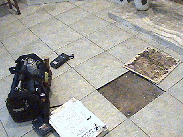
Moisture is unquestionably among the most serious problems relating to just about any type of floor covering installation, and resilient is no exception. The reasons why moisture can be a problem for resilient installations are many. First, mildew or an alkali condition associated with
the moisture can affect the color integrity of the floor covering. Second, moisture can have an effect on the bonding ability of the adhesive used in the installation. No resilient manufacturer is likely to recommend the use of its product in an area where a known moisture problem exists without eliminating it. And no one product is likely to solve a moisture problem all on its own. Moisture is a complicated problem, and solving it can involve taking a combination of measures. Therefore it's imperative that you determine if a moisture problem exists, determine the cause
of the problem, and then select the measure or combination of measures needed to solve the problem. Installations over bare slab, either on or below grade are most prone to complications due to moisture. There may be no apparent problem on casual inspection, but it's best to really analyze the surface with an adhesive mat test or a calcium chloride moisture test. If a slab surface does show evidence of a moisture problem, the installer might be tempted to simply use one of the many liquid or silicone sealers available on the market. That might be a mistake. Chemicals
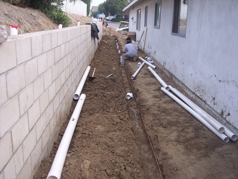
in some sealers could discolor the resilient over a period of time, and can cause significant bond failures. There are many new waterproofing agents on the market. It's a good idea to get a written warranty from the manufacturer. It's best to try to get to the cause of a moisture problem. For example, one common problem is caused by roof drainage downspouts. If a downspout empties too close to the foundation, the drainage water will eventually migrate into the slab. By diverting the drainage away from the building, the cause of the moisture can be eliminated. You can go ahead with the installation once the cause of the moisture is eliminated and the moisture significantly reduced. Some resilient floors have features that address normal moisture transmission that might remain, and are formulated to resist discoloration due to mildew or alkali.
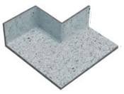
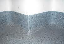
2. INSTALLATION HEAT WELD INTERGRATED COVEING
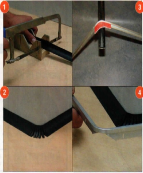
Flash coving of resilient flooring requires true craftsman-ship. In this issue, we will cover the installation procedures for an outside corner "V" plug, using a homogenous product.
Start with the installation of the cove cap and cove stick, using either a wood or vinyl cove stick. After cove cap and cove stick are installed, take your utility knife or sand paper, and round out the top area of the cove stick so that there is not a sharp point where the two pieces of cove stick come together at the outside corner. What you are trying to create is a smooth, round radius rather than a sharp corner on the cove stick.
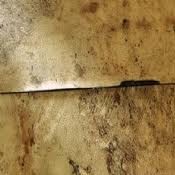
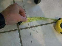
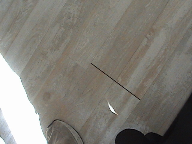
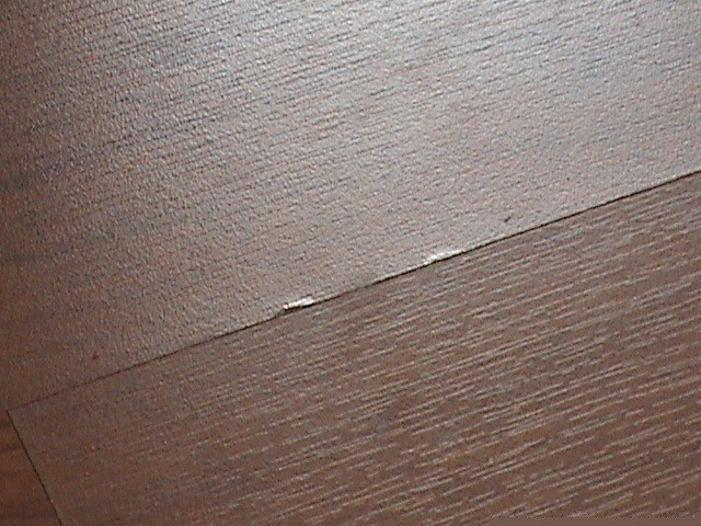
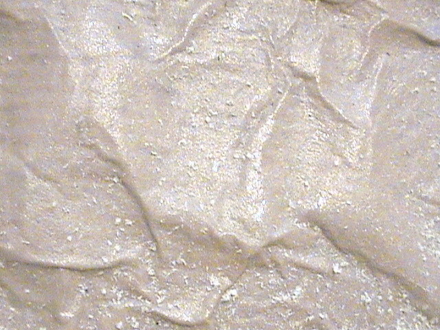
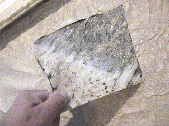
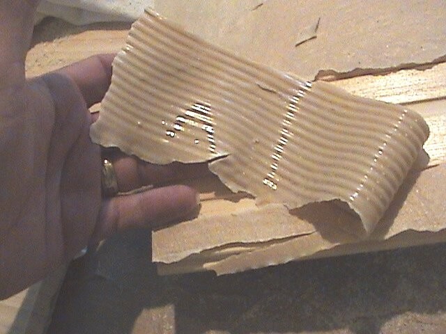
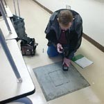
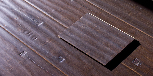
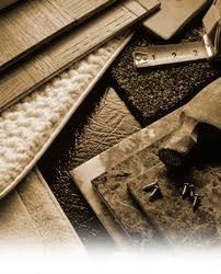
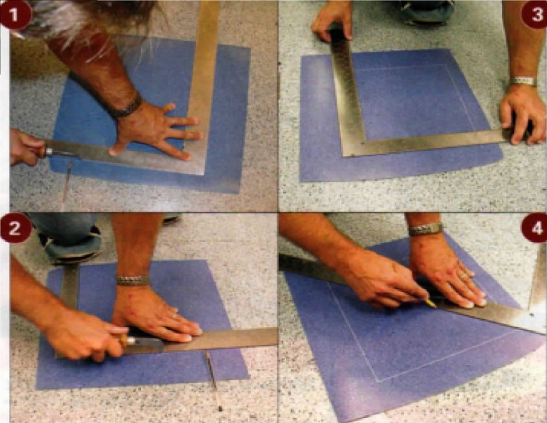
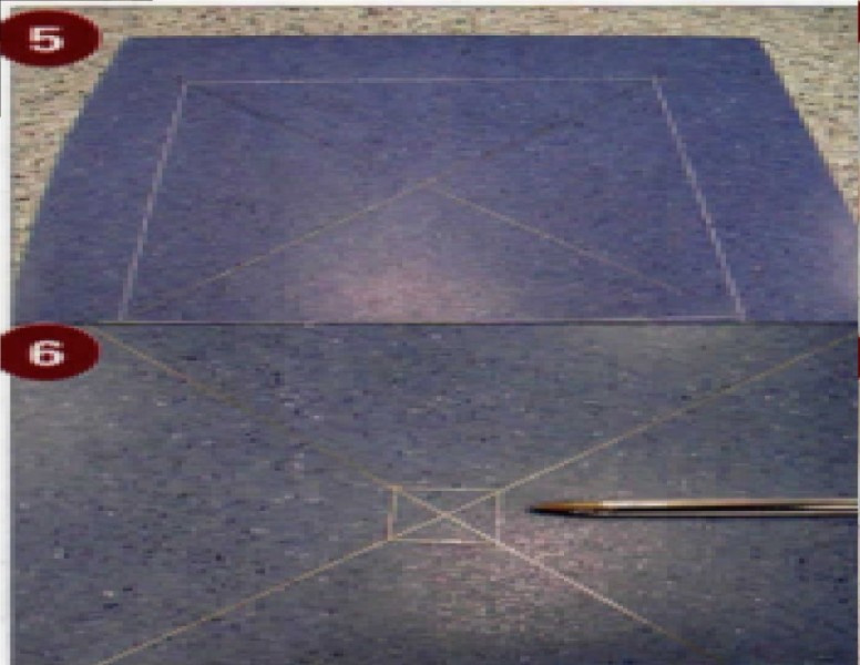
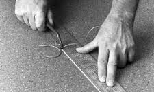
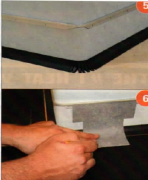
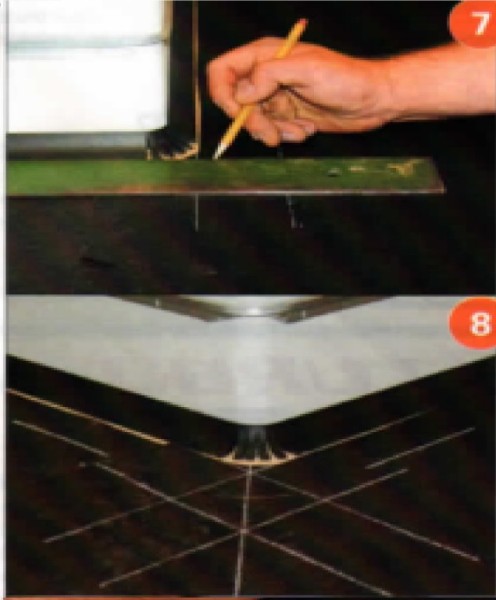
Once you have installed the cove stick and cove cap, you need to measure for the V plug. The procedure we will be covering creates four V plugs, since most installations require more than one V plug. To measure for a V plug, take a tape measure and measure the distance from the substrate to the top of the cove cap. Our module measured 5 V; inches from substrate to the top of the cove cap, so we will double the measurement to 11 inches. Take a piece of the material to be installed and cut a piece approximately 18 to 24 inches square; this will allow the square to lay flat on the material while cutting. Place the square on the product and mark, in this case 11 inches, on each side of the square and create an 11-inch right angle (Photo 1). Score the 11-inch right angle using a linoleum knife or a knife with a utility blade (Photo 2). Take the square and mark another 11-inch right angle to form an 11-inch square; mark and score (Photo 3). Once you have formed a square and scored all sides, take the square and make a pencil mark diagonally form corner to corner (Photo 4); repeat this step with the opposite corners, you should see four triangles (Photo 5). A 0.5mm mechanical pencil works best, but for photo enhancement we used a #2 pencil. From the intersecting point, mark one-half inch on each intersecting line to create a one-inch square box (Photo 6). This creates the V Plug without the point.
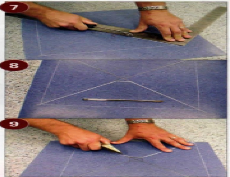
Place the square on a diagonal and score with a knife, repeat on the other diagonal, and finish scoring the lines that form the one-inch square. After you have scored the two diagonals and the one-inch square, groove diagonal lines and the one-inch square. Use a hand groover and the carpenter's square and groove two thirds the depth of the product, making sure to keep the score mark in the middle of the groove (Photo?). Make sure you keep enough pressure on the square to prevent movement.
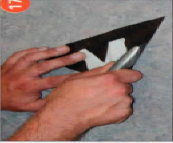
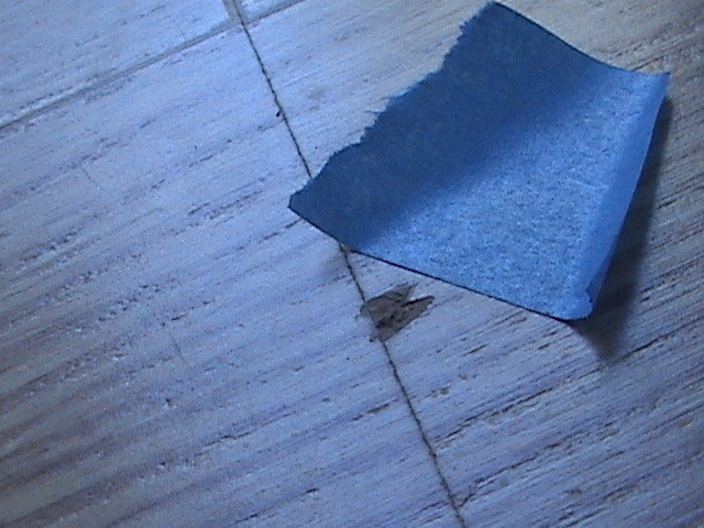
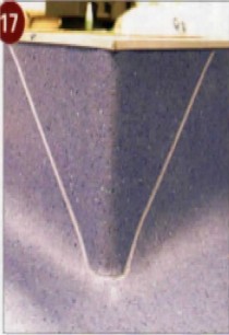
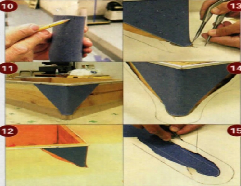
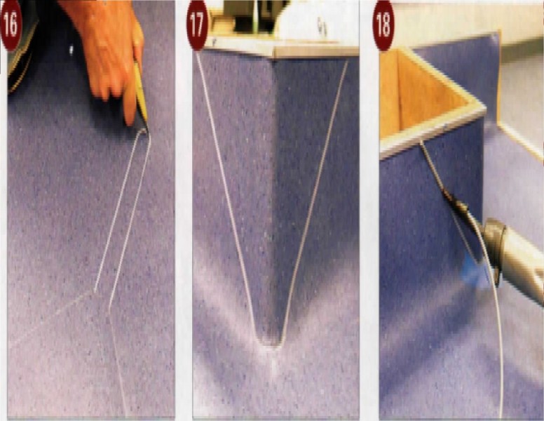
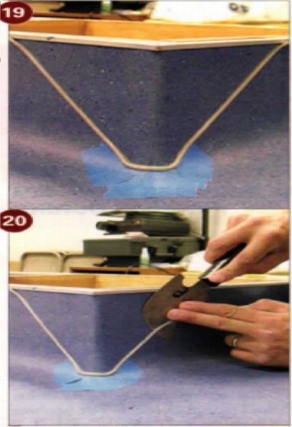
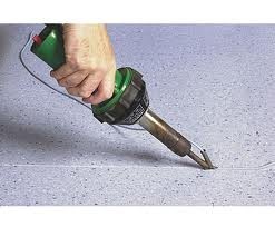
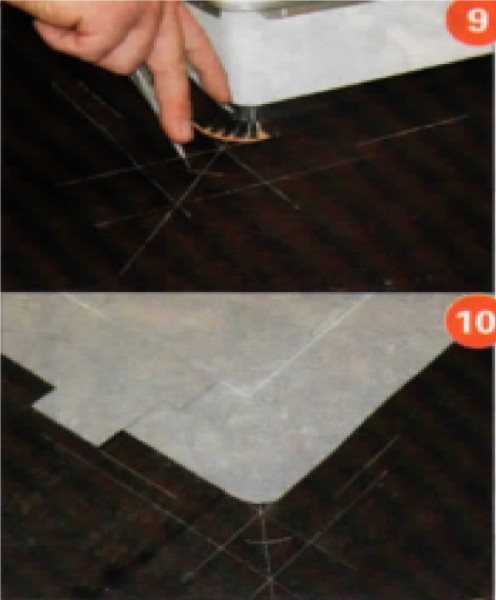
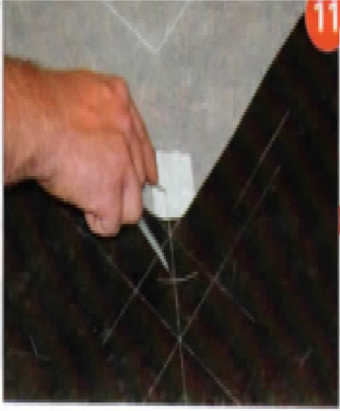
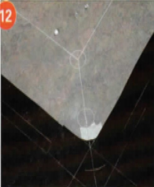
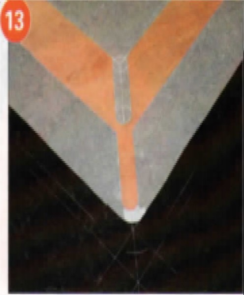
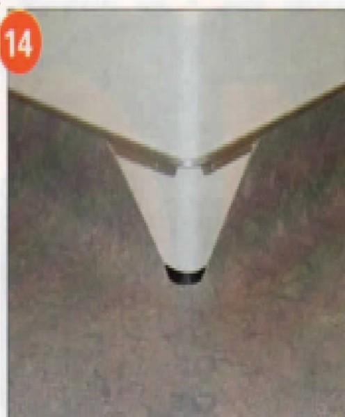
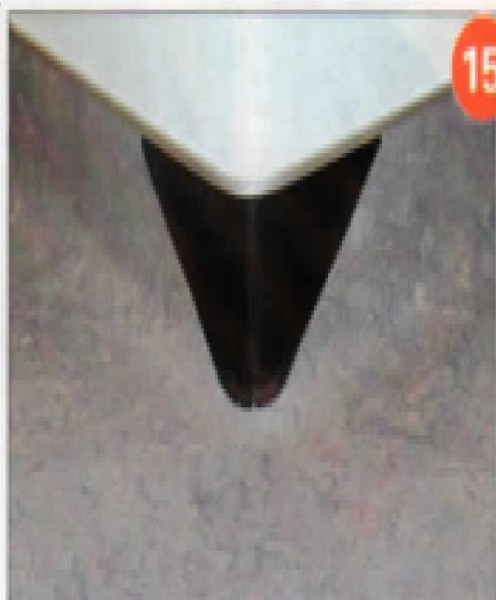
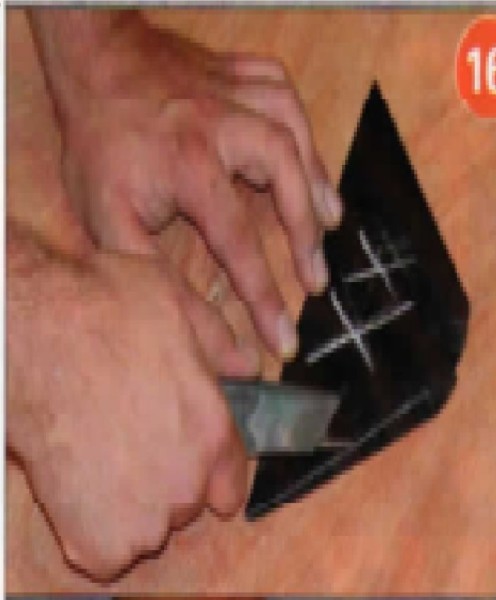
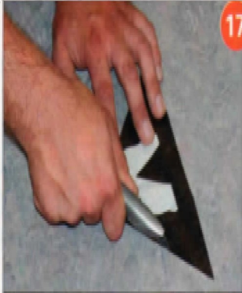
When you are finished scoring, you should have a triangle without the point (Photo 8). Do not groove the outside lines that form the box. Proceed to cut out the triangle along the score marks (Photo 9). Fold the V plug carefully in half and mark the center on top and bottom; this will help in the alignment of the V plug to the outside corner (Photo 10). Adhere the V plug to the outside corner with the appropriate adhesive. If necessary, heat the V plug with a heat gun to conform to the outside corner, and use a damp cloth to help shape the V plug (Photo 11) . Lay out and cut in the pattern felt, running the pattern felt up the walls that are to be flash coved and temporarily secure felt to the substrate by cutting windows into the felt and applying masking tape. Cut the felt paper 1/8-inch to 1/4-inch away from the V plug and the cove cap (Photo 12). Take a pair of dividers that are spaced 1/4-inch to 3/8-inch; you will need a narrow opening in order to accurately follow the contour of the V plug. If the dividers are too wide, you will not have a true fit. Scribe to the V plug, transferring the lines to the pattern felt maintaining a right angle with the dividers to the areas being patterned (Photos 13 and 14). You may want to use a different set of dividers that can be set to a wider spacing to pattern scribe areas other than outside corners of the installation. Once you have pattern scribed the area that you are installing, transfer, align, and tape the pattern felt on to the material. Transfer marks onto material with the dividers, making sure to stay at a right angle to the scribe marks (Photo 15). Once you have patterned out the material, score the scribe lines. Next, take the hand groover and carefully groove the radius and two sides that will be seamed to the V plug, two thirds the depth of the material, once again, making sure to keep the score line in the center of the groove (Photo 16). Cut out material and install. The corner should have a clean seam that is ready to be heat welded (Photo 17). Depending on the product, the amount of time will vary before heat welding can commence; follow the manufacturer's guidelines. Apply blue painter's tape to the wall above the cove cap and at the base of the V plug to minimize the potential of scorching the wall and material with the heat weld gun. Use the recommended welding rod and welding tip for the material. A con-trasting welding rod was used on this material for photo enhancement.
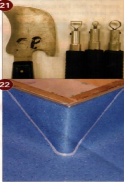
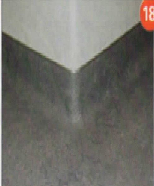
Clean the area of any debris and tools prior to heat welding, as once you start, you will need to heat-weld in one continuous motion. Make sure the tip of the heat gun is clean and do a practice run on a scrap piece to make sure the temperature of the heat gun is properly adjusted. Pre-heat the starting point by running the heat welding tool over the grooved area, making sure not to overheat, then proceed to heat weld the V plug (Photo 18). Once you have heat welded the V plug, you will need to trim the excess welding rod; this is called skiving (Photo 19). Generally, on a flat surface a skive plate is used to trim the majority of the excess welding rod, but this is not possible to use on a vertical, angled, V plug, so care must be taken to prevent gouging or slicing the material (Photo 20). I try to do a first pass with a quarter moon knife and an X-Acto type tool (Photo 21) while the material is just slightly warm on a vertical surface because the welding rod will trim easier. Also, I don't want to take the chance of pulling the welding material out by trying to trim all of the excess when the welding rod is completely cool. Don't attempt to do a finish skive at this point; all we are doing is reducing the amount of excess welding rod while it is still slightly warm. Once the material has cooled sufficiently, finish detail skiving using the quarter-moon knife and the X-Acto type tools. After you have finished, you may have some dull areas where the knife or X-Acto tools dulled the surface of the material; use the manufacturer's floor finish product to create a smooth consistent look (Photo 22). I would like to thank Scott Parks of Tri-West Distributing in Southern California for the helping hands.

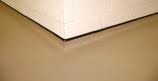
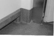
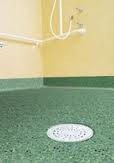
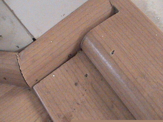
3. FLASH INTERGRATED COVING RADIUSED OUTSIDE
Flash coving, or self coving, resilient sheet goods is generally considered to be the most challenging type of installation for resilient installers. Throw In a rounded outside corner and it becomes even more challenging. The following steps describe how this can be accomplished using sheet linoleum.
Note: As with any installation, prep work will influence the finished job. Take the time to make sure all the wall surfaces are solid, smooth, and flat. The cove stick should be a quality, rigid or semi-rigid material that will adequately support the flooring material.
1. Install the cove stick: Mark the beginning and end of the outside corner radius on the cove stick. Using a miter box, make relief cuts approximately 1/8-inch apart between the marks (Photo l).Cut from the bottom of the cove stick to the back, taking care not to cut all the way through. Install the cove stick, making sure the cove radius is uni-form around the corner (Photo 2).
2. Install the cove cap: Mark the beginning and end of the outside corner radius on the cove cap. Insert a scrap of the material to be installed in the cove cap in the area to be bent; this will keep the cove cap from collapsing when bent. Form the cove cap around a pipe of similar radius as the outside corner (Photo 3). Bend slightly past 90 degrees; the final shape can be "fine tuned" on the actual corner. Remove the scrap and cut out the back of the cove cap with tin snips. Take care not to damage the face of the cap (Photo 4). Test fit and "fine tune" the bend if necessary, then install the cove cap (Photo 5).
3. Make the pattern: Cut scribing felt to fit for either the T-Template or Full Felt (scribing felt up the wall) scribing method. If using the Full Felt method, cut the felt away from the outside corner so that the entire corner and cove stick is exposed. Mark the pattern for the top of the cove cap on each side of the outside corner using standard scribing methods (Photo 6 - A T-Template was used here). Align a straightedge with the bottom of the cove stick on one side of the corner and mark the pattern on both sides of the straightedge at the corner. Repeat for the other side of the corner (Photo 7). Mark a straight line from the bottom of the cove stick through the corners of the box formed by the marks from the straightedge (Photo 8). This line is the center of the corner. Locate a point on the cove stick approximately 1/3 of the way down from the top, and in the center of the corner. Using dividers set at approximately 3 inches, strike an arc from the mark on the cove stick that intersects the corner center line (Photo 9). Make sure to save the divider setting on the pattern.
4. Transcribe the pattern: Transcribe the marks for the top or the cove cap. Take care not to mark past where they intersect at the corner (Photo 10). Place masking tape on the material at the bottom of the corner and, using a sharp pencil, extend the corner center line onto the tape. Using dividers set at the same setting used for scribing the arc in Step 3, mark a point along the center line from the intersection of the arc and center line (Photo 11). This point is the bottom of the outside corner fill.
5. Make the cutout for the outside corner fill: Scribe a line from the intersection formed by the lines for the top of the cove, to the point at the bottom of the corner. Measure up from the mark at the bottom of the corner approximately 3/4-inch along this line. Using that point as the center, scribe a circle that goes through the point at the bottom of the corner. The actual radius of the outside corner may vary from job to job, and will determine the best size for this circle. Experiment with trial cutouts made on scrap material to determine the best fit for the outside corners you are working with. Scribe another circle of the same radius at the top of the corner, using the intersecting lines at the top of the corner as the center (Photo 12). Scribe parallel lines tangent to the outside of the circles and cut from the top of the cove down around the radius and back to the top of the cove (Photo 13). This cutout forms the shape of the outside corner fill. Do not undercut the material in the radius of the circle.
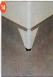
6. Install the field material: Use tape to reinforce the bottom of the corner cutout. Do not spread adhesive in the area of the corner fill. The test cutout from Step 5 can be used to mark adhesive spread lines at the corner. Install the field material,
carefully forming it around the outside corner (Photo 14). A heat gun on a low setting will make the material more pliable and help avoid damage at the bottom of the outside corner. Make sure the material conforms tightly to the radius of the cove stick.
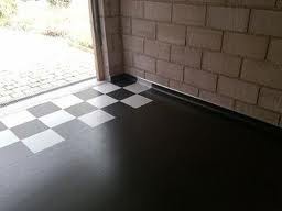
7. Fit and install the outside corner fill: Cut a triangular shaped piece of scribing felt slightly larger than the outside corner fill. Round off the bottom of the triangle and make three or four small relief cuts in the rounded area. Rub white chalk on the edge of the field material around the corner fill and carefully place-(he triangle of felt up in the cove cap, centered on the corner (Photo 15). While holding the felt tightly against the corner, carefully press along the chalked edges to transfer the chalk to the back of the felt. Remove the felt and cut along the chalk outline. Mark the side of the pattern that had the chalk on it (Photo 16). Place the felt pattern on a scrap of material with the marked side down. Align die top of the felt pattern with the machine direction (length) of the material and carefully trace around the pattern (Photo 17). Do not undercut the rounded area at the bottom of the fill piece. Carefully dry fit the fill piece and make adjustments if necessary. Apply adhesive and install the fill piece, again using a heat gun on a low setting to help form the material at the cove stick. Use tape to hold the fill securely in place while the adhesive is drying. Small scraps of material can be placed behind the tape where extra pressure is needed. After the adhesive has dried, remove the tape. Fill in any small gaps with a paste made by mixing powdered shavings from a scrap, and white glue. Wipe the corner clean with a damp cloth and finish it off by applying a thin coat of floor finish along the seam. A little patience and careful fitting will produce the finished outside corner shown in Photo 18. +
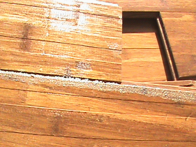
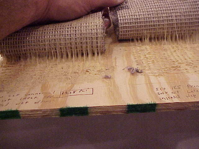
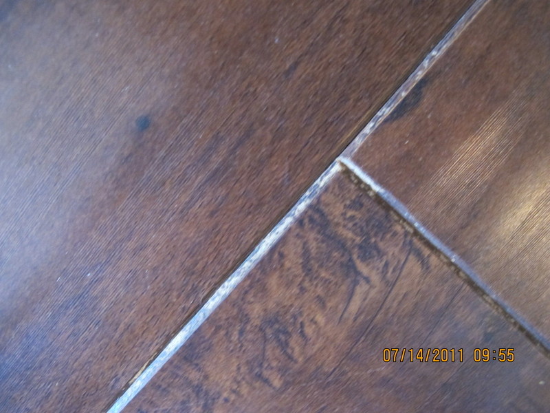
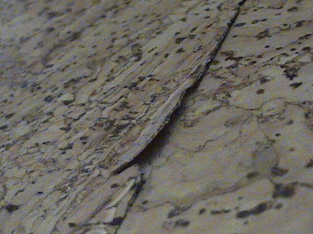
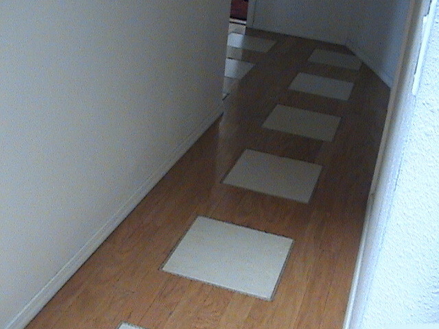
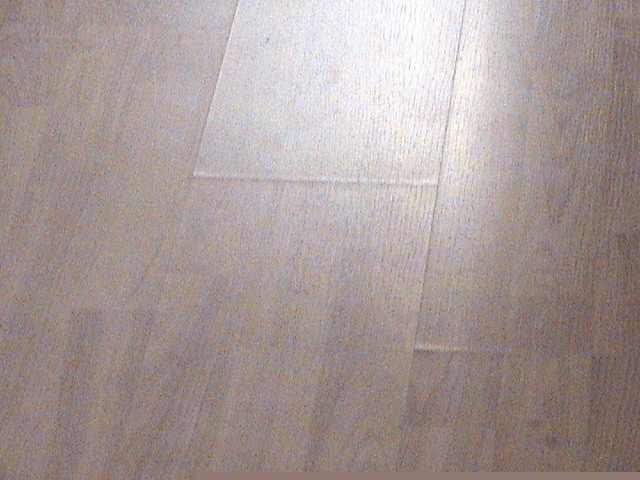
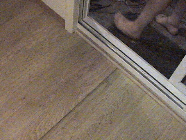
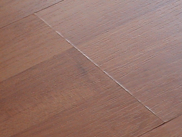
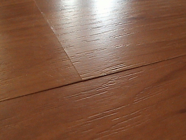
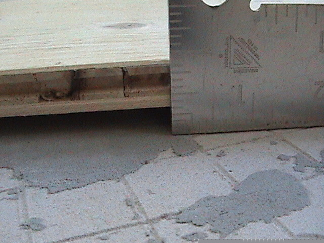
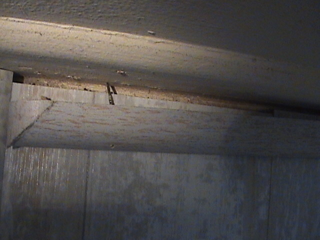
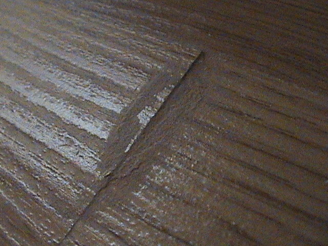
4. 30 KNOWN CAUSES OF JOINT (SEAM) TELEGRAPHING
30 KNOWN CAUSES OF JOINT (SEAM) TELEGRAPHING
1. Underlayment not held down tightly while being fastened to the subfloor.
2. Staples or nails are not long enough to secure underlayment properly.
3. Soft or punky subfloor
4. Wet subfloor (surface water may accumulate during construction).
5. Some waferboards or particleboards.
6. Installing undertayments over single floor systems (ie: %" tongue & groove).
7. Gun pressure set too high (resulting in staple blow-through).
8. Not enough staples or nails (2" on seam, 4" in field).
9. Wet floor patch (allow patch to dry thoroughly).
10. Floor patch net properly applied.
11. Glue forced between panels.
12. No expansion joint left between wall and underlayment.
13. Bouncing pneumatic stapler (using safety mechanism as trigger); seldom had this problem with mallet type (ackers.
14. Working itself loose over time (doesn't show up the next day).
15. Not enough glue, resulting in bubbled or released vinyl over underlayment joints or patch areas; approximately 75% coverage is needed to properly adhere vinyl to underlayment.
16. Too much adhesive open time, resulting in adhesive too dry to property adhere vinyl to underlayment. Adhesive will dry or set much faster over
the porous patch areas.
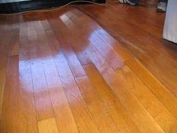
17. New vinyls are whiter, glossier, thinner (making underlayment imperfections more easily seen) and vinyl backings are still changing.
18. High or low floor joist.
19. Uneven subfloor - these must be sanded before %" underlayment is installed.
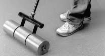
20. 75 or 100 Ib. Linoleum roller not used - must be rolled in both directions.
21. Cold sheet goods or cold adhesive. If floor covering is unrolled at a temperature below 65°F, a surface wrinkle may appear - this is known as piping. These wrinkles must be removed prior to
installation by bringing sheet goods up to 65°F for no less than 24 hours. Cold adhesive or cold sheet goods can affect both adhesive set-up and adhesive bond.
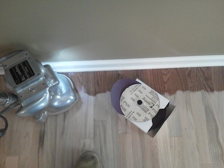
22. After fastening, thoroughly sand all underlayment joints with a belt sander until level. Hand sanding is not sufficient enough to correct any unevenness between panels.
23. Avoid over-sanding or cupping of the joints.
24. Patch all voids, gaps, gouges and chipped edges.
25. Patching all joints with a minimal amount of floor patch, but being sure patch is forced into all joint areas.
26. All patching compounds should be mixed with latex liquids, regardless if they are powdered latex solutions or not. Latex liquids are bonding agents and ensure the best adhesion and provide
maximum flexibility of patch.
27. Allow floor patch to dry properly and sand all joints level; some touch-up or a second coating may be needed, then sand again.
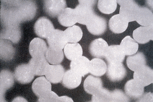
28. Make sure all patching is completely dry before installation of new vinyl. Wet patch may contribute to problems of mold or mildew discoloration.
29'. Wet patches are not totally stable and some may shrink or swell.
30. If joints are not property filled, adhesives may get forced into the joint area and could possibly be forced out. If panel expansion is experienced, this will also cause seam telegraphing.
JOINT TELEGRAPHING - TIME LINE
Probable cause of joint telegraphing if complaint happens for period after installation:
2 DAYS
Wet floor patch
Wet subfloor
Improper acclimation
CHECK
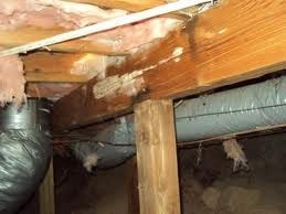
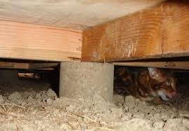
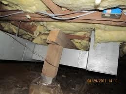
Subfloor, crawl spaces
Possible cold sheet goods
Over-sanding
Too much patch
2 WEEKS
Fastening problem
Wet crawl spaces
Wet subfloor (12°m.c.)
Movement in subfloor
Panels installed too tight
No spacing around wall perimeter or other fixtures
Jneven subfloor
Improper gluing of panel to subfloor
2 MONTHS
Improper fastening
Movement / home
Rolling heavy objects
Deflection in subfloor
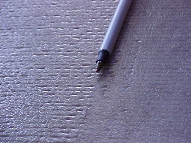
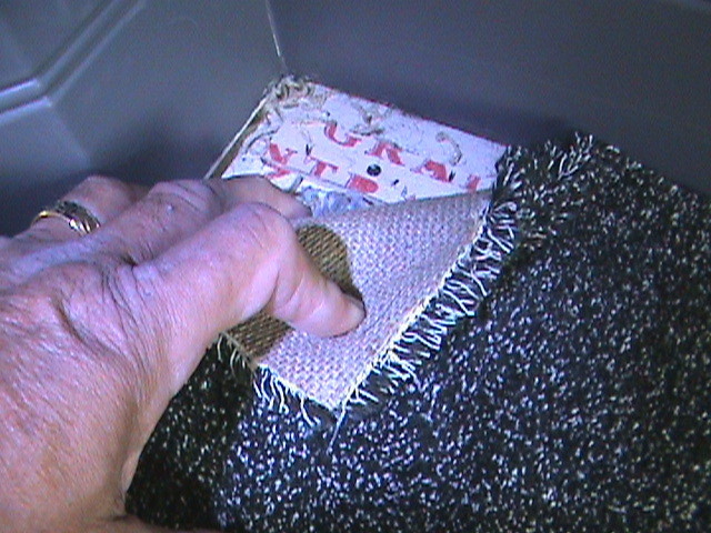
LOOSE VINYL TO FINGER:
Wet patch
Cold temperature
Too little adhesive
No vinyl roller used
Too much spacing between panels
Uneven subfloor