

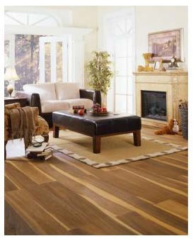
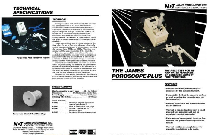
The National Institute of Certified Floor-Covering Inspectors (NICFI) is a
non-profit association of independent floor covering inspectors. NICFI members are expert flooring failure analysts and expert witnesses in flooring problems and failures.
NICFI members are experienced in the inspection and failure analysis of
woven carpet, broadloom carpet, resilient tile, rubber tile, cork tile, ceramic tile, resilient sheet vinyl, vinyl composition tile, LVT, hardwood, laminate, solid vinyl,
and specialty flooring materials.
NICFI members attend the annual NICFI Convention in Dalton, Georgia, to increase their knowledge and update their skills. The Annual Convention includes updates on indicative field testing
procedures, tools, products and product defects. The NICFI is the only Non-Profit Association in the Flooring Industry with membership comprised solely of Certified Floor Covering Inspectors.


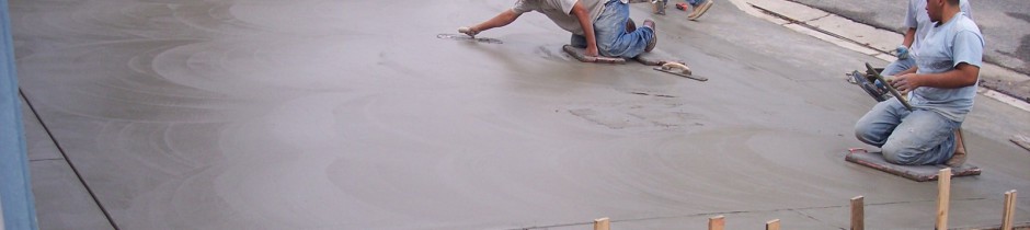
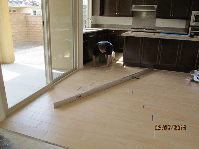
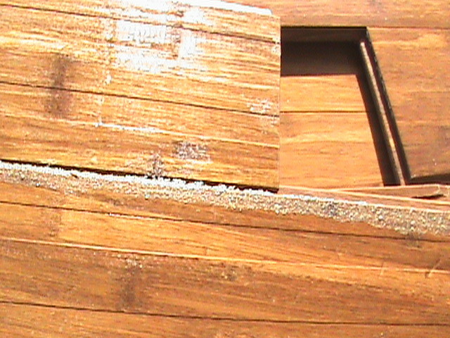
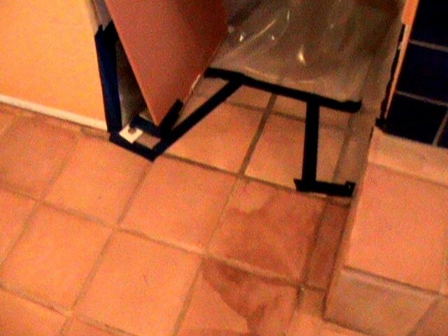
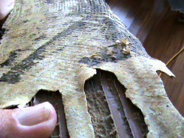
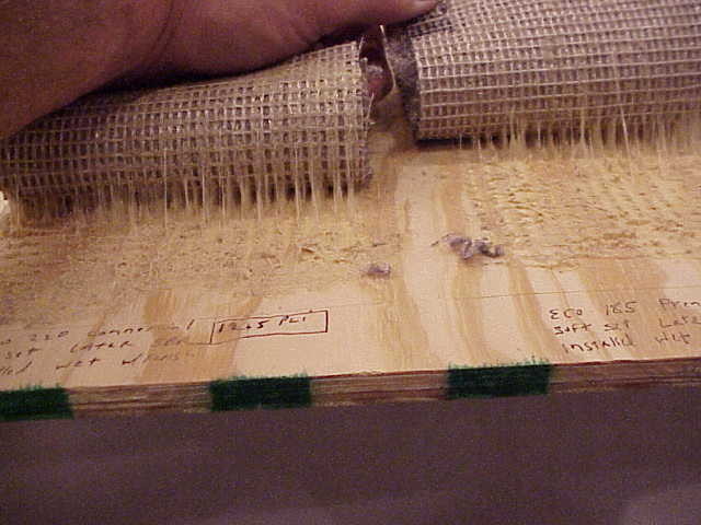
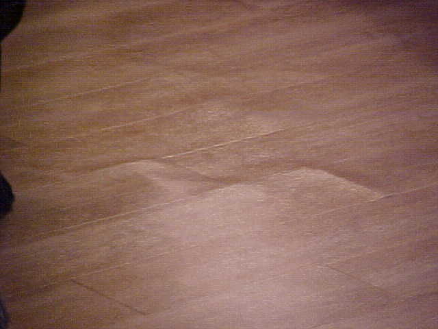
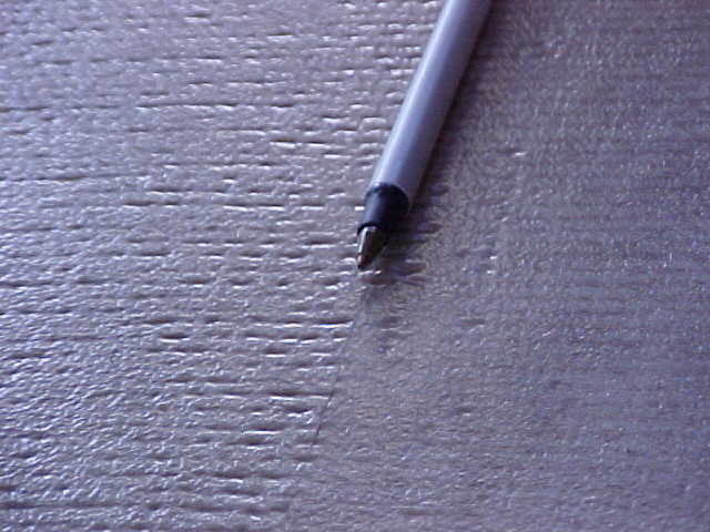
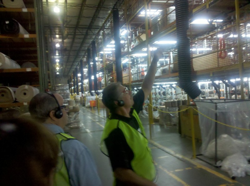
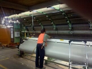
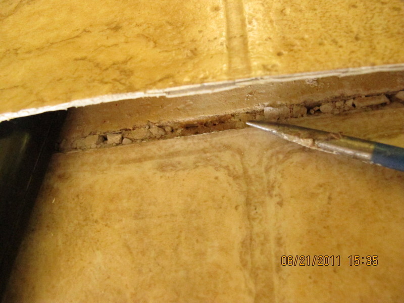
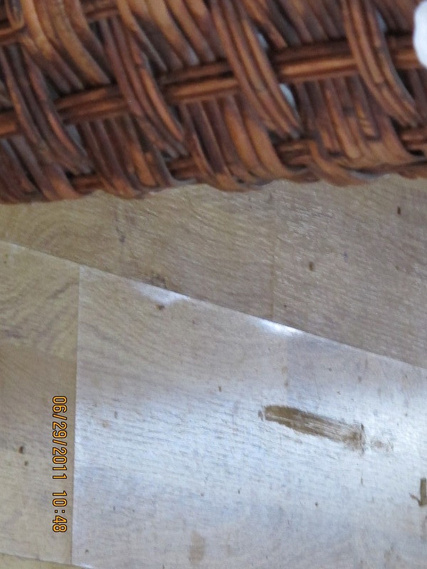
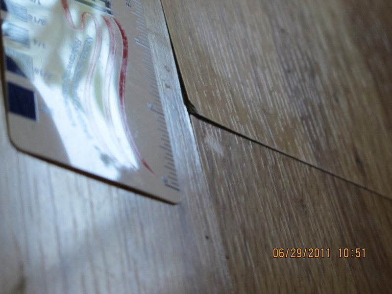
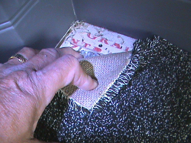
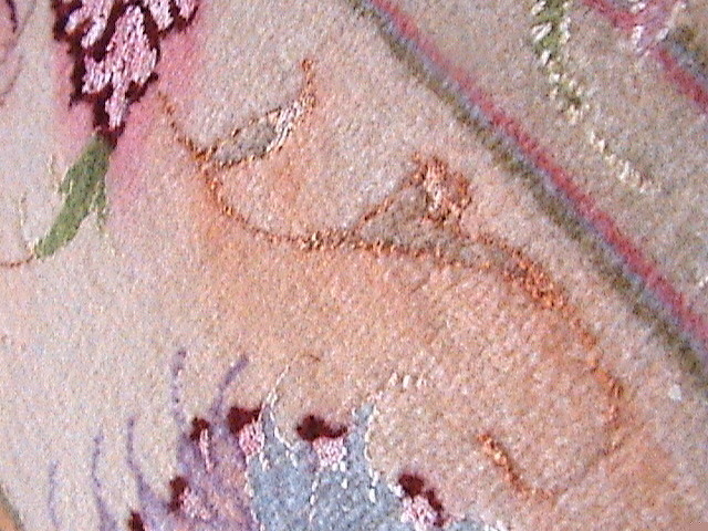
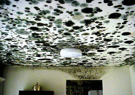
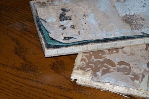
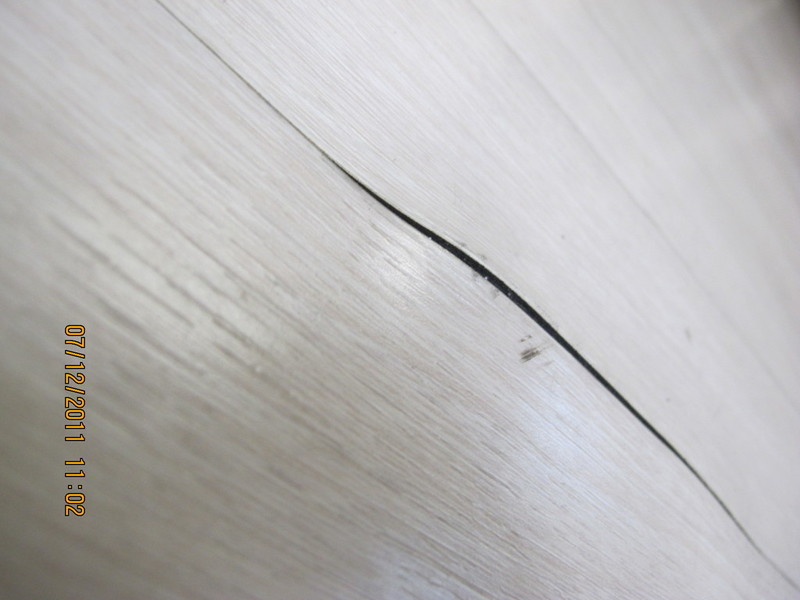
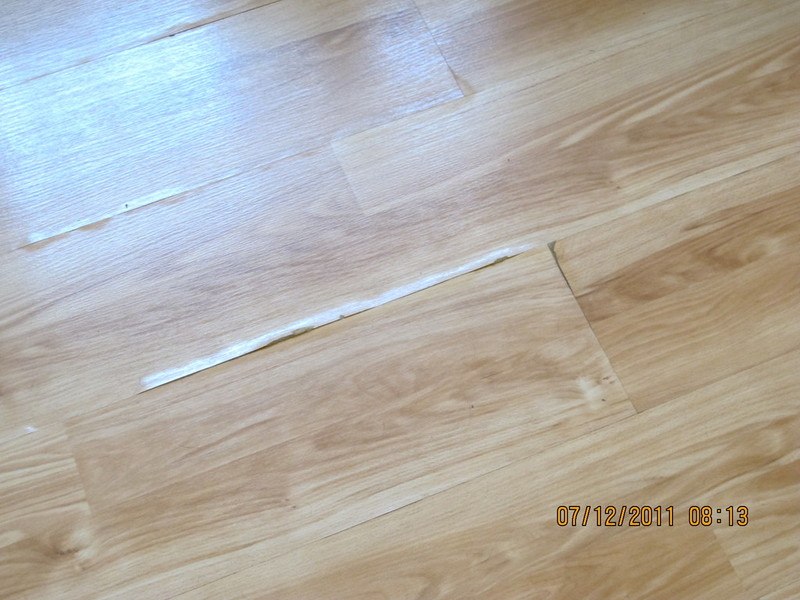
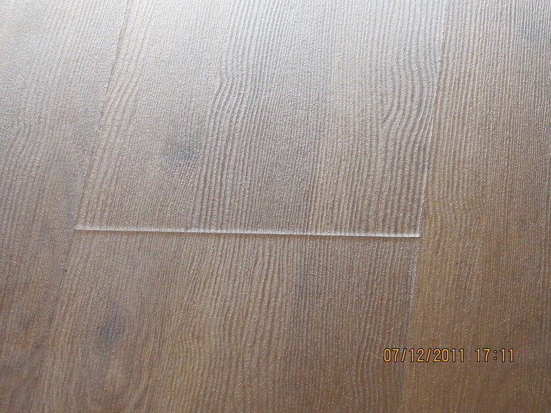
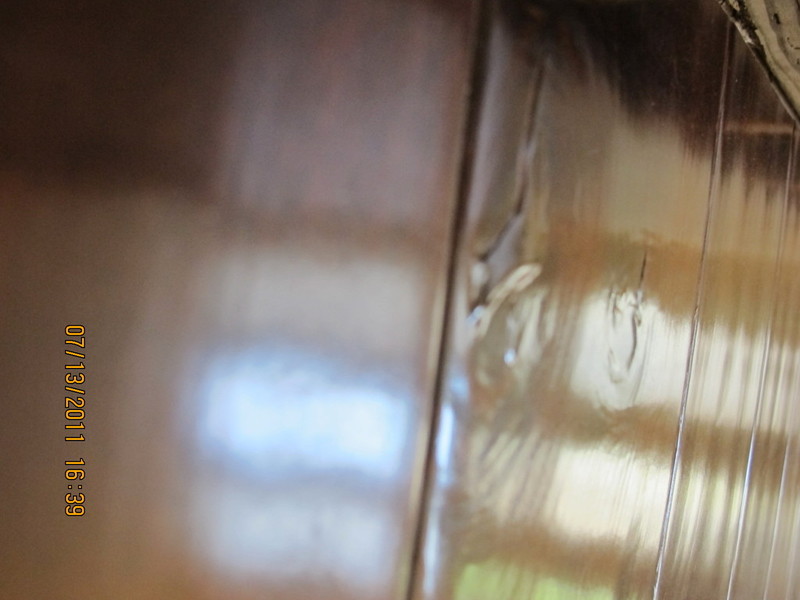
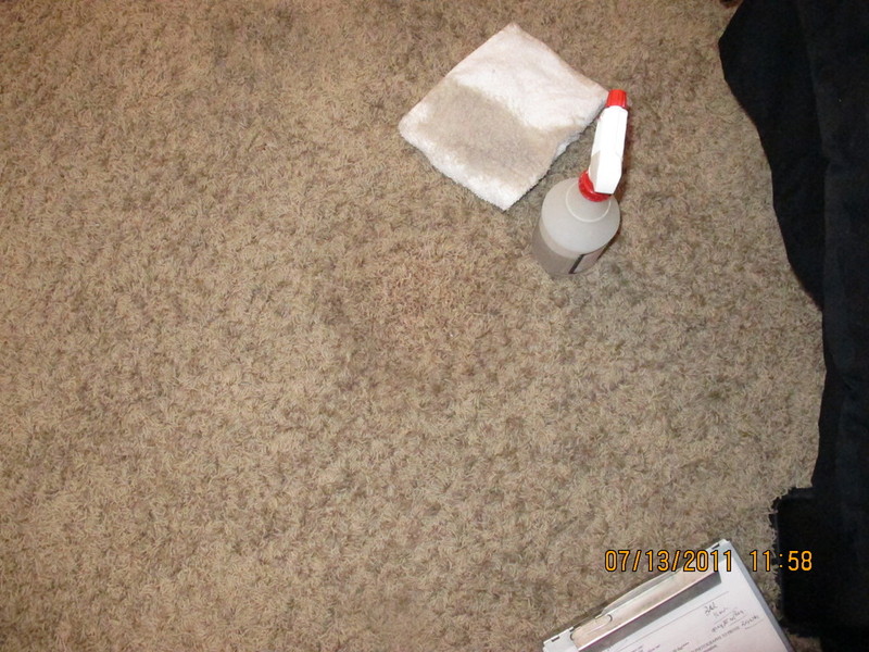
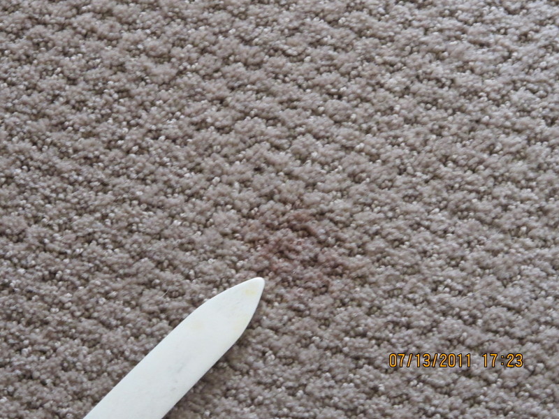
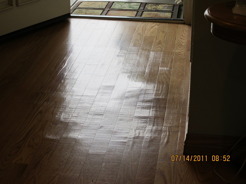
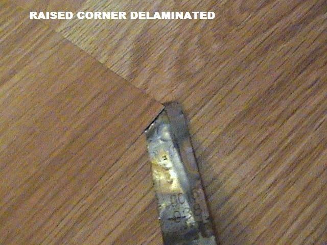
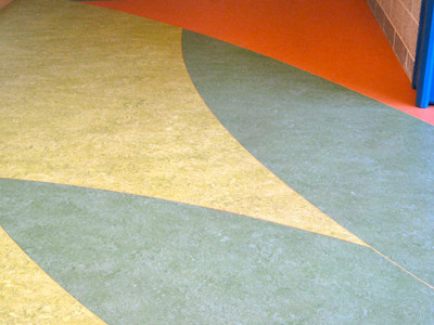
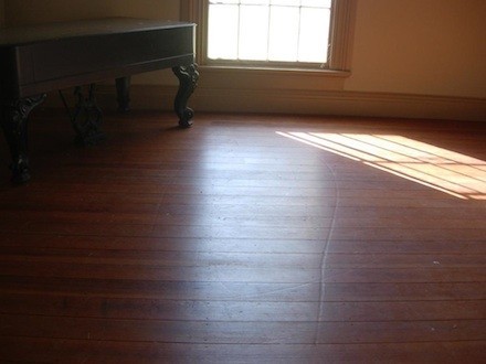
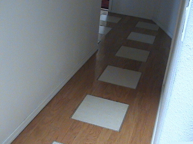
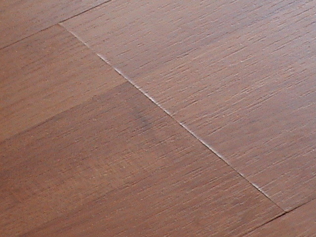
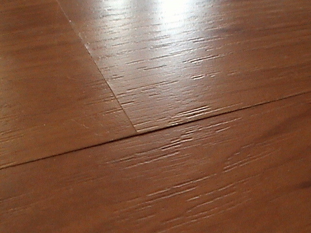
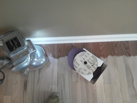
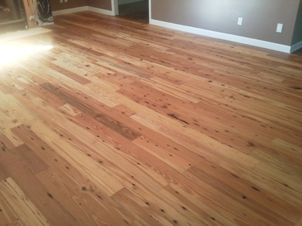
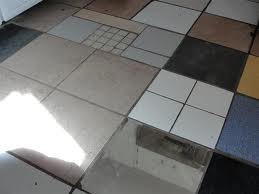
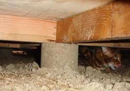
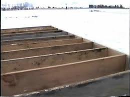
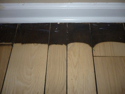
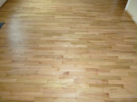
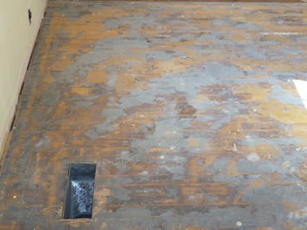
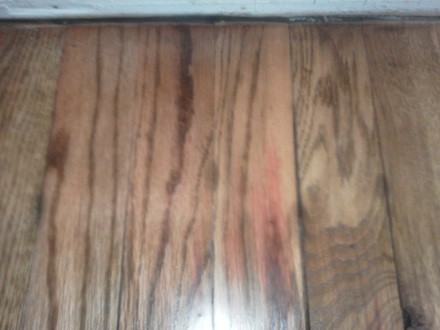
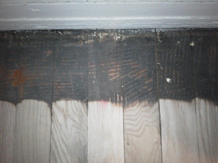
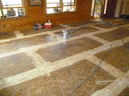
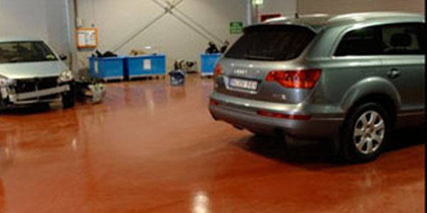
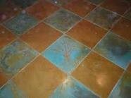
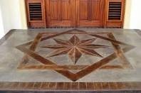
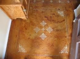
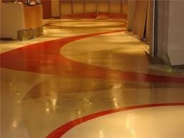
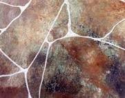
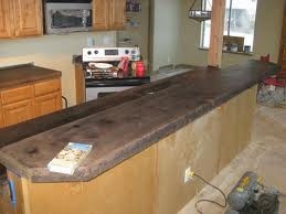
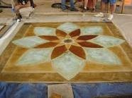
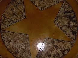
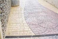
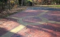
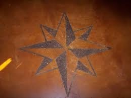
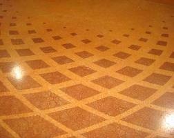
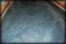
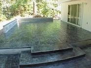
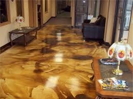
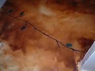
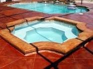
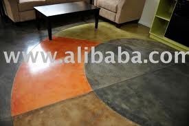
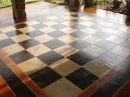
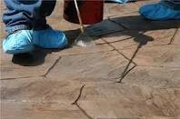
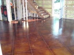
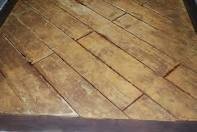
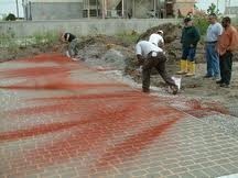
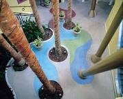
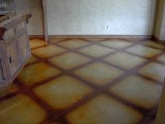
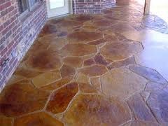
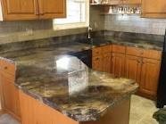
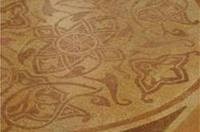
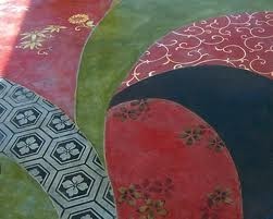
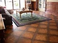
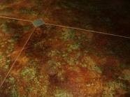
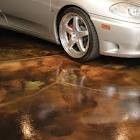
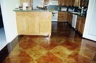
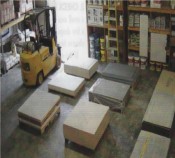
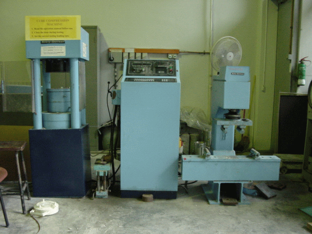
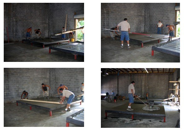
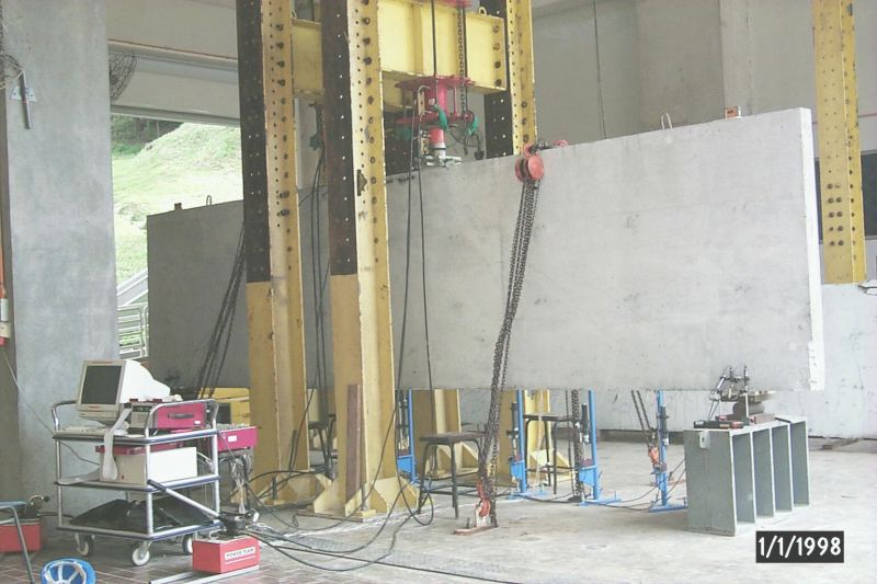
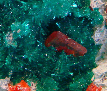
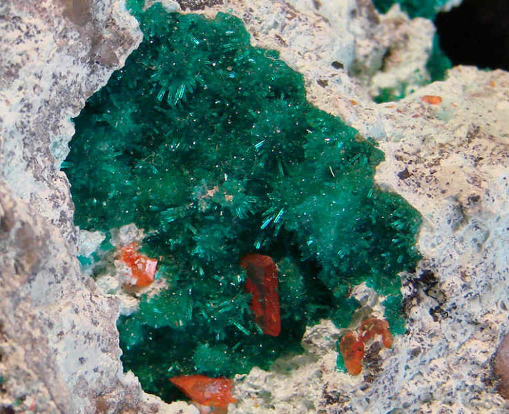
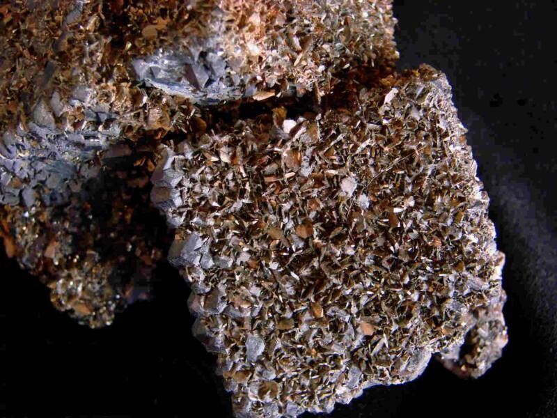
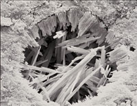
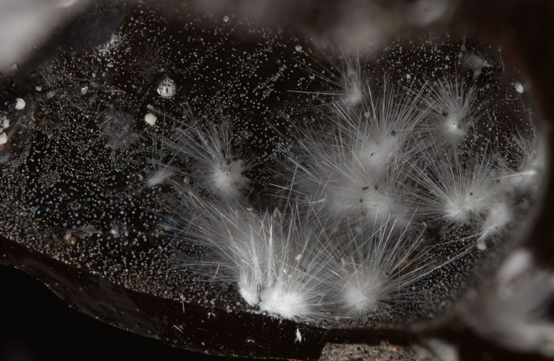
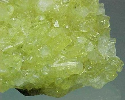
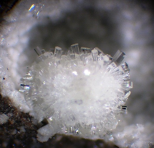
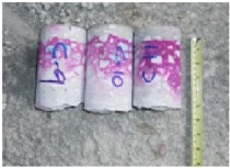
PHOTOS
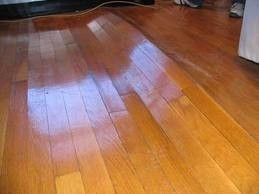
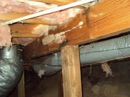
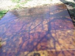
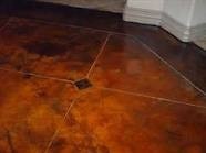
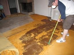
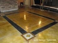
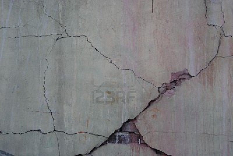
IS THIS YOUR COMPLAINT?
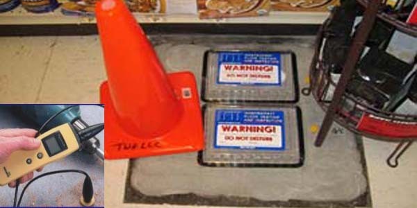


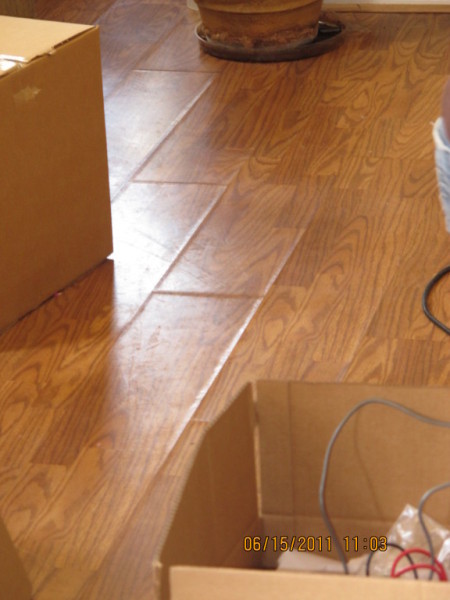

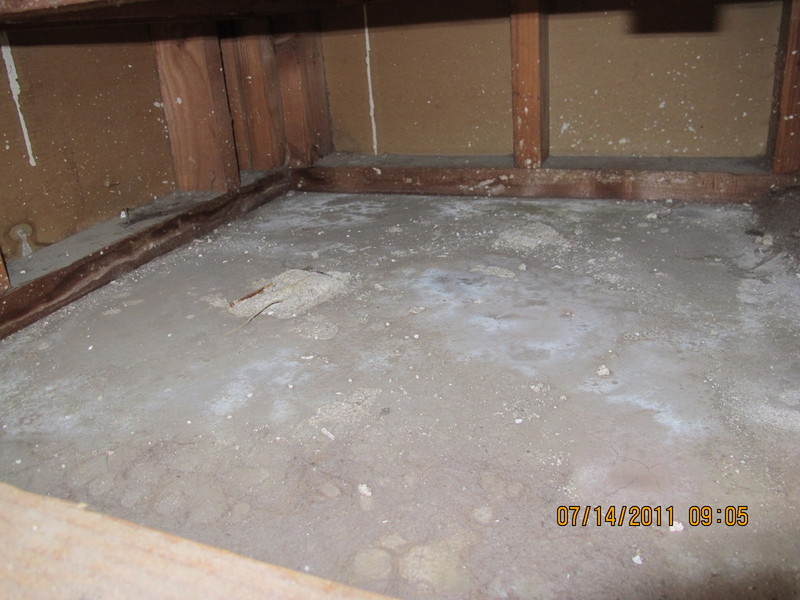


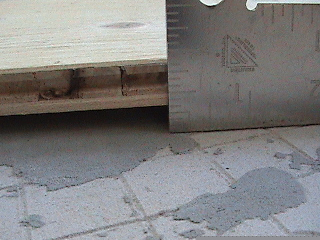
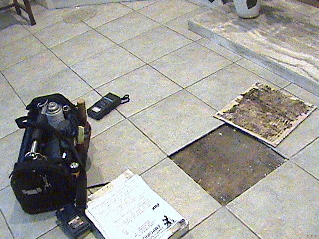


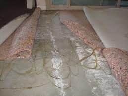
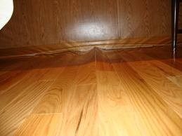
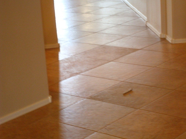

CONCRETE call for moisture testing service
CONTENTS BELOW INCLUDE:
- SELF-LEVELING CONCRETE FLOOR-PREP - VIDEO
- CONCRETE QUALIFICATIONS
- CONCRETE MATRIX
- WATER TO CEMENT RATIO - WIKIPEDIA
- ACID STAIN CONCRETE
- RH or RELATIVE HUMIDITY MOISTURE TESTING PROTOCAL
- BACKERBOARD
- CONCRETE CORE EXTRACTION AND TESTING
- ETTRINGITE
- PHENOLPHTHALEIN TESTING
- CARBONATION
QUESTIONS FORWARD TO: floorcovering@cox.net
1. SELF LEVELING - VIDEO

SELF-LEVELING - CONCRETE FLOOR-PREP VIDEO
2. CONCRETE QUALIFICATIONS
Resilient Flooring Failures: An Architect's Perspective
by Scott Parish
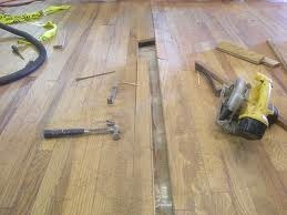
In 1994, we began to see wholesale failures of sheet vinyl floors and spot failures of resilient tile floors on our projects. The big Problems began with a sheet vinyl floor of approximately 560 m2 (6,000 ft2) that developed a mushy bubble in the middle of the floor. This quickly spread outward in all directions until the flooring was only adhered at the perimeter. Cutting into the floor revealed the adhesive had re-emulsified. After the replacement floor failed in the same manner, a very costly membrane system was installed on top of the slab, prior to the third flooring material installation.
Initial Response
The two consecutive failures motivated us to find out what was going on and how to avoid this problem in the future. Information available at the time from industry seminars and publications
suggested the problem was due to vapor emission from the concrete slab. Following recommendations from these seminars and publications, we altered our interior concrete slab details and
specifications to ensure they provide a sealed vapor retarder to prevent contribution of vapor from moisture inherent in the soil under the slab use
27 600 kPa (4,000 psi) concrete design mix for dense, less permeable concrete reduce water/cementitious ratio to a maximum of 0.48 to reduce water of convenience and promote less permeable concrete
through increased cement content (water of convenience in the concrete is a major contributor to vapor emission) do not allow admixtures that add salts and retain water (calcium chloride) wet cure
slabs for 14 days minimum, maintaining a film of water under curing blanket, to fully hydrate the cement at the surface; this significantly reduces permeability at the top of the slab by closing off
the capillaries, making them discontinuous, and also restricts the ability of condensed water to pool at the top of the slab require construction practices that promote drying and reduce water
contribution after placement:
Continuing Difficulties
After implementing these changes, we saw a drop in vapor emission, as measured by the calcium chloride test. However, only one project achieved the 3 lb (lbs per 1,000 ft2 per 24 hrs [1.4 kg per 42
m2 per 24 hrs]) limit required by most flooring manufacturers. We believe the addition of fly ash to the mix contributed to the success of this project. Of course, our attempts to be so restrictive
resulted in other concrete quality issues. We now are more sensitive to the causes of slab curling and the different methods of dealing with it. We are also on the lookout for combinations of
admixtures that could potentially limit compressive strength or have other deleterious effects. By this time, flooring installers were refusing to install products on slabs exhibiting more than 1.4
kg (3 lbs) vapor emission. General contractors were backing away from responsibility for the issue, reminding us how carefully they had followed our specified material and installation procedures
(that's what we get for specifying means and methods!). Flooring manufacturers were withholding warranties, and owners were becoming unwilling to accept change orders for topical membrane products.
They wanted to know why they should have to pay extra to get the trouble-free installation they thought was specified. No one had time to wait for the slab to dry. Of course, we weren't interested in
accepting the liability either.
Vapor and Alkalinity Control Products
We had been very reluctant to specify topical membrane products to reduce vapor emission because they are very costly. However, because of the impasse on many construction projects, we began to
investigate these products in late 1998. The investigation process turned out to be an interesting education in physics, sales tactics, and product warranties. It was during this investigation that
the critical issue of alkalinity came to the forefront. Rather than vapor emission itself, it was the pH level of the moisture collected under the adhesive (through water vapor movement and dewpoint)
that was the primary cause of adhesive failure. This new information filled a gap in our understanding. It also provided a rational basis for evaluating the claimed performance of membrane systems.
As a result of this process, we established criteria for evaluating these systems:
Present Practices
Today, we are proactive about the possibility of flooring failures and high calcium chloride test results on our projects. We evaluate each type of flooring product against failure and specify an
appropriate membrane product on an allowance basis. We educate our clients about the realities we all face in concrete slab and flooring installations, emphasizing the fact that we must take
reasonable precautions to prevent project delays, unanticipated costs, and failures (dollars spent now are cheaper than multiplied dollars spent later). We specify proven products and draw the line
on substitutions. After a program of calcium chloride tests is completed, we establish the actual level of protection required, the systems available to meet the actual needs of the floor, and the
owner's warranty requirements and budgetary constraints. During construction, we pay close attention to concrete mix design and placement and curing practices. We are looking forward to the day when
adhesive manufacturers will develop alkali-resistant adhesives and flooring manufacturers will establish a more realistic warranty limit for vapor emission.
Concrete Extras
Temperature always affects chemical reactions. With few exceptions, chemical reactions will double for every 18-degree rise in temperature. Curing of concrete is the opposite of drying. It is impossible for an on-grade slab to have a "hydrostatic" problem.
All water has vapor pressure dependent on temperature and humidity (even frozen water has vapor pressure). Contrary to popular belief, moisture tends to migrate to the cooler, damper side, not the warmer, drier side. Under-slab vapor barriers do not prevent moisture from reaching the slab. Moisture can migrate through the holes created by screed stakes pipe penetrations. Concrete is extremely hygroscopic and, in the right conditions, can actually absorb enough moisture from the atmosphere to appear wet (dewpoint/condensation). If the interior section of the concrete is cooler than the surface, moisture will migrate toward that cooler, damper area. There is a common misconception that once moisture cannot enter concrete from the soil, moisture will no longer be a problem. Hydration means to chemically combine with water. How concrete hardens is still not completely understood.
In any livable environment, concrete is never dry. Vapor emission volume does not mean vapor pressure. Vapor emission volume is a measurement of vapor emitted from the concrete surface. It does not indicate where it came from. Vapor pressure is created by differences in temperature and humidity between concrete surface, concrete interior, and the use environment. When the internal humidity of concrete drops below 80 percent, the curing process essentially stops. Moisture problems in the majority of floors are not waterproofing problems.
Water is in its densest form as a liquid.
On average, it takes approximately 870 days for the average concrete slab, 102 mm to 127 mm (4 in. to 5 in. thick), to "dry out." The worst slab conditions for flooring are a high water-cement ratio, lack of proper cure, and a hard trowel surface.
Below is a listing of water-cement ratio mix designs and the time necessary to properly wet the concrete. Cure time is the time necessary to develop a discontinuous capillary pore structure in the concrete.
|
Water-Cement Ratio 0.40 |
Cure Time 3 days |
Moisture-Related Flooring Failures: Dispelling the Myths
by Robert Higgins
There is a lot of information circulating as to why flooring failures exist, and why they seem to be increasing in frequency. Most of the information is a mixture of half-truths, innuendo, and fairy tales. Typical of these fairy tales is how vapor pressure builds creating "backpressure." Another myth is vapor pressure alone can cause flooring failures. This is not true. Many people think water moves to the warm side of a floor, yet the opposite is true. Another common myth is "modern adhesives are more sensitive to moisture." There is no empirical data to support such a statement. If the above are myths and fallacies, what are the true causes of moisture-related flooring failures? There are three basic influences to flooring failure: moisture, alkalinity, and alkali-silica reactions.
Moisture
Although moisture is an ingredient in failures, there is no linear correlation between moisture levels and the majority of flooring failures. The exception is when the moisture levels are high enough
to either interrupt or prevent curing of the coating and adhesive. High-vapor emission levels or dewpoints generally create high moisture levels. Although these two activities are completely
unrelated to each other, the end result is similar.
Vapor Emission.
Vapor emission is the movement of water in its gaseous state. Water vapor responds only to temperature and humidity. As a result, the vapor emission levels are entirely dependent on the differences in relative humidity and temperature between the concrete surface, concrete interior, and the use environment. Vapor pressures are often blamed for vapor emission problems, but the actual vapor pressures are so low, they can only be calculated, not measured. In fact, vapor pressures rarely exceed 3.4 kPa (0.50 psi) and, under livable conditions, cannot even achieve pressures exceeding 6.9 kPa (1.0 psi). Once a relatively impermeable material covers the floor surface, the influence of room/interior environmental humidity is essentially eliminated. Underneath the flooring material, the humidity moves to equilibrium and the humidity under the flooring material(s) typically ranges between 80-100 percent. If the adhesive has not fully cured and the concrete temperature is within 5 degrees of dewpoint, condensation can occur preventing the adhesive from curing. Whether this is a temporary or permanent effect is largely dependent on three basic influences: the progress of adhesive cure, concrete porosity, and concrete permeability.
Dewpoint
Dewpoint may well be the least understood and least appreciated influence in flooring failures. Dewpoint effects can strongly resemble vapor emission, but are largely controlled by a natural hydrological cycle. Dewpoint can occur as the concrete temperature cools. Moisture begins to condense in and on the concrete surface. The condensed moisture might not be visible if the interior section of the concrete is cooler than the surface as the moisture will tend to migrate to the cooler interior. If the surface continues to cool and reaches dewpoint, the concrete surface can literally become saturated with moisture. This has potentially devastating effects on many types of adhesives and coatings, even though the majority of the industry is virtually unaware of this phenomenon.
Alkalinity
The deleterious effects of alkalinity have been identified, yet the exact mechanisms of damage are completely misunderstood. The ways alkalinity can damage adhesives and coatings are complex. Each type of degradation is dependent on one or more of the following: pH level; concentration of alkalinity; sensitivity of compound and components to alkalinity levels; and availability of moisture, temperature, and humidity; and permeability of applied goods. For example, an adhesive may have excellent resistance to moisture, yet as the pH levels increase, the tendency toward re-emulsification may increase exponentially. Situations exist when a seemingly modest pH increase can govern whether or not an adhesive can continue to function usefully. If a product were resistant to a pH of 9.0, doesn't it suggest the adhesive would continue to resist, if at all, an increase of pH to a level of 9.2? Keep in mind the pH scale is logarithmic. Each full digit increase (e.g., 7.0 to 8.0) is a tenfold increase in pH. This would suggest a seemingly inconsequential increase of 9.0 to 9.2 is nearly twice as alkaline.
It is important to note soluble and emulsifiable are completely unrelated terms. Most adhesives are emulsions that lose their ability to suspend or dissolve in relatively pH neutral water after curing. Water-soluble is the continuing ability of a solid to readily dissolve in a relatively pH neutral water medium. Emulsions can become soluble as the pH increases. An increase in pH can also separate the solids component of an adhesive from its plasticizer. This prevents the adhesive from functioning as intended and appears as a moisture-related flooring failure.
Alkali-Silica Reactions
Alkali-silica reactions (ASR) are sometimes considered a "newly discovered" phenomenon, but are actually well-known to those in heavy concrete construction. Their discovery dates back to the 1940s.
ASR is a worldwide problem and is extremely costly. Its occurrence is somewhat unpredictable and not completely understood. The majority of research to date has been focused on the structural
significance of its destruction and is often referred to as "concrete cancer."
The correlation between low-level ASR and flooring failures was not considered until our research (in-house) found many parallels between mysterious flooring failures, site conditions, and ASR. In fact, the information was so startling that we were reluctant to go public with it until we were certain of its influence.
ASR occurs when strongly alkaline cement actually begins to dissolve sand and rock within the concrete. The chemical reaction creates a gel material that in turn creates tremendous pressures in the pores of the concrete surface. The amount of hydraulic pressures was estimated in a 1953 study to be approximately 3400 kPa (500 psi). A later study more precisely determined the pressures to range from as low as 1700 kPa (250 psi), up to 10 300 kPa (1,500 psi). This activity helps to explain the tremendous pressures witnessed within sheet goods and epoxy floor systems. It also is a much more plausible and scientifically responsible theory than the vapor pressure (up to a pressure of 6.9 kPa) and fabricated "backpressure" theories.
What cannot be covered in this article are moisture problems that are not really moisture problems at all (e.g., blue, gray, and red stains in vinyl, VCT curling [when the center of VCT is still bonded], and many others). Yet some moisture experts continue to fix many problems with unnecessarily expensive and inappropriate repairs. These repairs are not only a waste of time, resources, and money, they contribute to the ongoing myths surrounding what should be a science-based and logical approach.
3. CONCRETE MATRIC
The matrix
The matrix is formed by the binder and the aggregate. The binder, cement, consists mainly of lime, silica, alumina and iron oxide. During hydration heat develops during the acceleration stage, which lasts about 24 hours. During the retardation stage, which lasts about 28 days, the hydration sequence is retarded. About 1/3 of the hydration products consist of calcium hydroxide which does not take part in forming the cement gel, the binder.
Normally about three-quarters of the volume of the matrix is occupied by aggregate. The properties of the matrix are of course influenced by the properties of the aggregate. The properties depend on the petrology, mineralogy, particle shape and texture, mechanical properties, specific gravity and porosity. The aggregate may contain deleterious substances like organic impurities, clay and other fine material, salt, and unsound particles.
The aggregate shall be graded so that the matrix gets maximum density. The voids between the coarse aggregate shall be filled with smaller particles. The grading shall also result In a good workability of the fresh mix.
The properties of the hardened concrete are affected by the properties of the mix in the fresh stage. The fresh mix shall be workable, be possible to compact, surround the reinforcement
and fill out the mould without segregation of the constituents and have as little bleeding as possible. The fresh mix gradually converts to the hardened stage, the workability decreases and the
strength of the matrix is built up. Cracks can develop very easily during this phase (see the figure). The cracks can be initiated by outer or inner forces. One example of an inner force is plastic
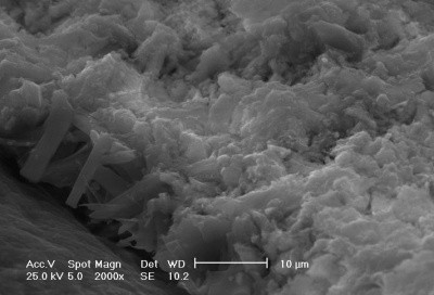
shrinkage caused by rapid evaporation. PHOTO#1
Relation between mouldability and age and relation between strength and age. The setting depends on the
evaporation and the hydration of cement. Factors as cement content, water content, the temperature of the mix and the temperature and relative humidity of the ambient air, admixtures and porosity of
the aggregate are all affecting the setting. For a 1: 3 mortar with a water/coment ratio of 0.5, the shriakage Is 0.4 % if the temperature is 520 ° C and the relative humidity 50 percent and the wind
velocity 1.0 m/s. During this setting time, the modulus of elasticity increases with increasing strength. During curia`', keeping the concrete saturated or as nearly saturated as possible during the
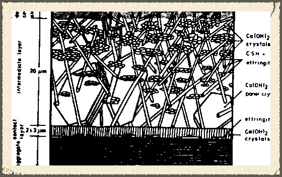
setting time, is very essential for the properties of the hardened product. The cement paste is not homogeneous. It contains pores of different sizes and weak zones can develop for instance in the
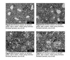
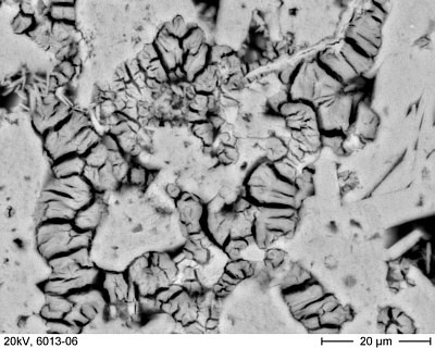
phase boundaries between cement paste and aggregate particles or reinforcement material, inter alia, due to water segregation in the fresh concrete state. PHOTO #2
Structure of the phase boundary between cement paste and an aggregate. When concrete is fully compacted, its
strength is taken to be inversely proportional to the water/cement ratio. PHOTO #3
The relation between strength and water/cement ratio. The tensile strength of concrete is low, less than 10 %
of the compressive strength. The type of aggregate and the moisture content have influence on the tensile strength. The tensile strength of concrete is about 2 MPa. The flexural strength of concrete
is affected by the dimension of the tested specimen, the surface of the aggregate maximum aggregate size, temperature and moisture gradients. The flexural strength of concrete is about 5 MPa.
The impact strength is related to the tensile strength of concrete and the brittle behaviour of the material. The impact strength can be increased by lower water/cement ratio, high volume of
aggregate, small maximum aggregate size and crushed aggregates. The impact strength of concrete is about 2 kJ/m². PHOTO #4
Typical stress-strain curve for concrete. A characteristic value of the modulus of elasticity for concrete is 30 GPa. The
strain at failure is 0,01 - 0,02 %. The drying shrinkage is caused by withdrawal of water. The main factor affecting shrinkage Is the amount of water available for evaporation from the concrete, i.e.
how much water has been added to the mix. PHOTO #5
Relation between the water content of fresh concrete and drying shrinkage. The dimension of the concrete structure, the relative
humidity of the ambient air, and the time affect the shrinkage.
Concrete also undergoes shrinkage due to carbonation and this shrinkage is in the same order of magnitude as the drying shrinkage. The thermal coefficient of expansion of concrete is in the
magnitude of 13 x 10(-6)/°C. The fibre Fibres can be classified as shown below. PHOTO #6
Fibre classification chart. PHOTO #6A
Properties of some fibres. There are three main factors which can cause partial or complete deterioration of the natural fibre. They include: * long exposure to moisture, * stress corrosion, and * exposure to aggressive environment. The concrete is aggressive. Its alkalinity is high. PHOTO #7
Schematic sketch of the decomposition of sisal fibres In concrete. The middle lamella Is dissolved by the alkaline pore water In the concrete. In carbonated concrete, the alkalinity is low and therefore the fibre is not decomposed. Fibres are added to concrete In length up to 25 mm ( in some cases even 75 mm ) in the mix or as long fibres between layers of matrix.
The composite The properties of fresh fibre concrete are dependent on the properties of the
matrix, the type of fibre added, the fibre length and the fibre volume. The workability of the mix is changed, compared to the workability of matrix without fibres. Extra water is needed to maintain
constant workability. If the volume of added fibres is high, balling of the fibres may occur. The fibre length and thickness do also influence the balling. The thinner the fibre, the shorter must it
be to avoid balling. The addition of fibres enhances the cohesion of the fresh concrete and makes It possible to mould a product In a simple manner. Depending on the properties of the matrix and of
the fibre, the suitable fibre volume and fibre length can be found In pretests. If, for instance, the intended product is a corrugated roofing sheet, it should be established that the thickness does
not change during the setting time. Concrete Is extra weak during the first few hours, before the hardening process has given the material a certain strength. Water evaporation can cause Cracking,
due to plastic shrinkage. It is the same process which occurs when mud dries. It has been known for thousands of years, that this cracking can be limited or completely avoided by reinforcing the
material, for instance sun-dried bricks with straw. The incorporation of fibres in concrete can have a similar effect. But it is important to point out that concrete can be protected against plastic
shrinkage by stopping the water evaporation by an effective cover or by water spraying on the surface of the concrete. Constituents in the fibre material or on the fibre surface can cause retardation
of the cement hydration, and even affect the resulting strength of the fibre concrete. The harmful substances can be removed by properly cleaning the fibres, but in most cases it appears that the
normal fibre processing will give satisfactorily clean material. The main advantage of fibre reinforcement of concrete is the improvement of the fracture toughness, the impact, flexural and tensile
strength. PHOTO #8
Diagram of composite The composite Is elastic until the first crack has developed. This point, the limit of
proportionality, is not influenced by the fibres or only very limited. The occurrence of the first crack is therefore mainly determined by the properties of the matrix. If we use chopped fibres, the
flexural strength or modulus of rupture of the composite will be the same as the value obtained at the limit of proportionality, i.e. the flexural strength of the unreinforced concrete.
As can be seen in the figure, the modulus of rupture and the flexural strength of the composite reinforced with long fibres can exceed the limit of proportionality or flexural strength of the
matrix. But this means that the composite is cracked and the design load should therefore not exceed the limit of proportionality. The fracture toughness and impact strength of the composite is
considerably higher than in the case of short fibres, compare the area under the stress- strain curves. The compressive strength of the composite Is not at all affected by the addition of natural
fibres. If fibres which are not clean are used, the compressive strength can decrease. The incorporation of fibres may require extra addition of water which results in a higher water/cement ratio and
therefore a lower compressive strength. The water tightness of the composite Is not affected by the incorporation of fibres. But as is the case with the compressive strength, the water tightness can
be Influenced in a negative way If the water/ cement ratio Is Increased to achieve a good workability of the fresh mortar mix. Drying shrinkage of the hardened composite Is only linked to the water
content of the fresh matrix. The fibres can give a better crack distribution, smaller crack widths, but larger number of cracks. Again, it should be pointed out that the incorporation of short fibres
may require more water in the mix to obtain good workability which will increase the shrinkage. Properties like thermal conductivity, sound transmission, fire resistance, water absorption, linear
expansion. Moisture movements and temperature movements are not influenced by the incorporation of a few percent by volume of natural fibres. The natural fibres are protected against microbiological
decay in the matrix because of the high alkalinity of the pore water. Constituents of the pore water, for instance calcium hydroxide, penetrate the fibre and "mineralize" it. it is not known what
happens to a fibre in a crack, possibly there is a crack width limit within which the fibre is protected against microbiological decay.
The high alkalinity of the pore water results In a chemical attack on the fibre and causes a reduction or even nullisation of Its strength. Fibres In carbonated concrete, where the alkalinity of the pore water is low, are not decomposed chemically and seem to be protected against microbiological decay. The carbonation of the matrix is linked with a shrinkage. This shrinkage is of the same size as the drying shrinkage. The carbonation process is slow and this allows the creep of the matrix to play a role. The carbonation shrinkage causes micro - cracking and cracks can sometimes be seen on the surface of the carbonated concrete. The natural fibre does not play any or only a very limited role in this crack formation. With time the carbonation front moves Inwards Into the concrete and if we have a thin concrete product, it can be completely carbonated within a few years. The microcracking can have a negative Influence on the flexural and tensile strength of the composite. The addition of fibres in the fresh mortar may require more water In the mix to obtain good workability and this leads to a higher water/cement ratio, a faster carbonation process and a bigger carbonation shrinkage. Research in this field to clear the effects of the carbonation on the properties of thin natural fibre concrete products is recommended.
The tile Concrete tiles have been used on buildings for at least 80 years and the experience with them has been good. The concrete tile is not reinforced. Nowadays, they are normally manufactured of a very dry sand- cement mix with very low water / cement ratios. The thickness varies between 10 and 20 mm. Extrusion is used in the production process. In 1983 Parry introduced a S-shaped pantile with the dimensions 500 x 250 x 6 mm. The tile is light and easy to handle. The production process Includes the use of a vibro-screeding machine which secures a good compaction of the product. Short fibres are included in the fresh mortar mix to give higher cohesion. The long term behaviour of this thin product is not yet known. Two out of four producers of this tile report no cracking. In Sri Lanka and Brazil thicker tiles, 10 - 30 mm, are produced. The concrete tile seems to be an Interesting rooting element. Further development concerning the shape of the tile and the need of fibres in the tile is recommended.
The sheet Natural fibre concrete cannot directly substitute for asbestos cement. The flexural strength of natural fibre concrete is only 25 per cent of that of asbestos cement. Many sheets have been produced with dimensions common for asbestos cement products. Several instances of cracking have been reported and the dimension of sheets have changed to smaller sizes and thicker products. Still the cracking seems to cause problems and the need for repair or replacement of roofing streets already placed on a roof. The roofing sheet must be regarded as an unreinforced element. The use of short or long fibres seems not to have any different Influence on the long term behaviour. In Tanzania production of 70 000 m2 roofing sheets per year will be initiated in 1986, using a concept with long fibres and a manufacturers guarantee of durability. Further development concerning the roofing sheet, suitable dimensions and properties, is recommended.
The load on roofing structures A roofing element is subjected to many different types of loads. During production and curing we have the plastic shrinkage phenomena due to water evaporation. Later, the drying shrinkage of maybe 0.5 % may cause internal stresses and cracking. During handling, demoulding and transport cracking can occur. Storing and transporting In the wrong way, for instance piled on each other, may also result in too high stresses and cracking. During installation on the roof, the element also has to take static and dynamic loads. On the roof, stresses may be concentrated at different points or lines on the roofing elements. Deformations in the timber support may also cause stress concentrations in the element. For Instance, a temperature cycle from maybe + 10° C in the night and + 70° C on the day results in a movement of 0.7 mm per meter. The moisture movements caused by rain and sun also initiate movements in the elements which have to be taken into consideration. These movements may cause too high stresses and therefore cracks. The moisture movement of the natural fibres is bigger than that of the matrix, which may result in internal stresses, especially if the volume of fibres is high and the fibres are utilized as reinforcement (long fibres). If the fibres are decomposed due to chemical attack, also new stress situations may occur. Finally, the carbonation process in the matrix also leads to a shrinkage and micro crack development.
The quality control The control should comprise a check on the cement (no lumps), on the fibres (clean so that they do not contain "sugar"), that an account on the addition of constituents to the mix is made that the compaction is well done, that product shape, thickness and surface finish are acceptable, that the curing Is started immediately after casting in a proper manner and continued for one week, that possibly 10 percent of the products are tested in a non-destructive load bearing test and maybe 1 percent of the products are tested to failure. The fixings should always be checked. If the water/cement ratio is below 0.6, there is no need for a control of water tightness.
For further research The following items should be the subject of further research:
- What is the optimal shape of a roofing element made of concrete considering the non existence of a reinforcement ?
- Might the tile be produced without fibres?
- What consequences would this have on the shape of the tile ?
- Is it possible to use locally available pozzolanas as a partial substitute of cement ?
- Can the curing procedure be improved in an appropriate way ?
- Is it possible to use natural fibre as a reinforcement in the long term and to produce self supporting roof structures ?
4. WATER TO CEMENT RATIO - WIKIPEDIA

The water–cement ratio is the ratio of the weight of water to the weight of cement used in a concrete mix and has an important influence on the quality of concrete produced. A lower water-cement ratio leads to higher strength and durability, but may make the mix more difficult to place. Placement difficulties can be resolved by using plasticizers or super-plasticizers.
Often, the water–cement ratio is characterized as the water to cement plus pozzolan ratio, w/(c+p). The pozzolan is typically a fly ash, or blast furnace slag. It can include a number of other materials, such as silica fume, rice hull ash or natural pozzolans. The addition of pozzolans will influence the strength gain of the concrete.
The concept of water–cement ratio was developed by Duff A. Abrams and first published in 1918, see concrete slump test.
Concrete hardens as a result of the chemical reaction between cement and water (known as hydration, this produces heat and is called the heat of hydration). For every pound (or kilogram or any unit of weight) of cement, about 0.25 pounds (or 0.25 kg or corresponding unit) of water is needed to fully complete the hydration reactions. This requires a water-cement ratio of 1:4 often given as a proportion: 0.25. However, a mix with a w/c ratio of 0.25 may not mix thoroughly, and may not flow well enough to be placed, so more water is used than is technically necessary to react with the cement. More typical water-cement ratios of 0.4 to 0.6 are used. For higher-strength concrete, lower water:cement ratios are used, along with a plasticizer to increase flowability.
Too much water will result in segregation of the sand and aggregate components from the cement paste. Also, water that is not consumed by the hydration reaction may leave the concrete as it hardens, resulting in microscopic pores that will reduce the final strength of the concrete. A mix with too much water will experience more shrinkage as the excess water leaves, resulting in internal cracks and visible fractures (particularly around inside corners) which again will reduce the final strength.
The 1997 Uniform Building Code specifies a maximum 0.50 water-to-cement ratio (1:1) when concrete is exposed to freezing and thawing in a moist condition or to de-icing chemicals, and a maximum 0.45 water to cement ratio for concrete in severe or very severe sulfate conditions.
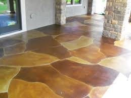
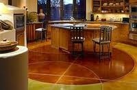
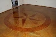
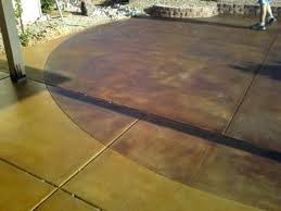
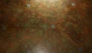
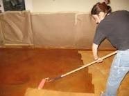
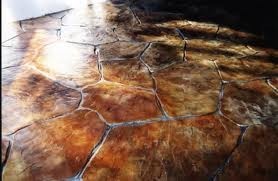
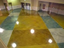
5. ACID STAIN CONCRETE
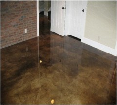
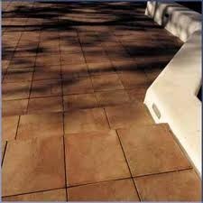
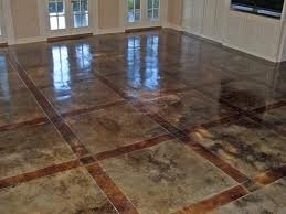
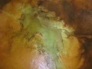
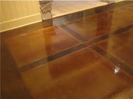
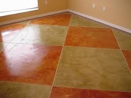
Acid stain concrete is an old technique that has recently seen a resurgence in popularity. Concrete floors are known to be durable, low maintenance, and incredibly ugly. If you learn how to acid stain concrete floors you can keep the durable, low maintenance surface while turning your ugly gray surface into a beautiful work of art. Most acid stains are going to be earth tones. This includes many shades of browns, dark reds, and greens. These earth tones will give your floor the look of expensive stone or marble, for significantly less.
If you are a non- do it yourself type of person you can hire a contractor to do your acid stain concrete job. For a basic job you will most likely pay around $4 per square foot. If you want a more elaborate and intricate pattern (multiple colors and designs) it will cost you anyplace from $4-$10 per square foot. If you just want a basic job through it is suggested that you do a do it yourself. Instead of paying a declarer $4 per square foot, you can get it done for $.50-$1.00 per square foot, and it will only take a few hours over two days to complete the job. Even if you are a DIY novice, you should be able to handle this type of project. Here are four steps on how to acid stain concrete.
Get Your Materials
You need to make sure that you have all the materials necessary before starting the job. Since you will be working with a weak acid it is essential that you protect yourself fully. This means wearing long sleeves and long pants, protective eye wear, a face mask, and gloves. Other materials necessary include: Acid concrete stain, sealer, concrete cleaner, broom, wet-vac, sprayer, paint tray, and a roller.
Prepare The Surface
Since the acid stain is semi transparent any blemishes or cracks on the concrete will show through. Hairline cracks can give your acid stained floor more character, by anything else should be repaired. You will need to clean the concrete to the best of your ability, the better you get it to look now the better it will look after you apply the stain.
Apply The Stain
There are a few ways to do this step, but I prefer to use an all plastic sprayer. One person should spray on the acid stain to the concrete while the other follows behind and brushes it in with a broom. This will leave brush strokes so the sprayer should go over the area again. Repeat this process until the whole floor is covered.
Wash The Floor
After the floor has had the proper time to oppose it is time to wash the floor with a baking soda and water solution in order to neutralize the acid concrete stain and remove any excess residue. You should go over the floor with this solution astatine least twice.
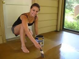
Apply The Sealer
Once the floor is completely dry you should apply 2-3 coats of sealant with your paint roller. As soon as the final coat is dry you can begin using your beautiful new floor. This is a simplified guide on acid stained concrete floors. Click this link for a complete, detailed, step-by-step guide on how to stain concrete floors.
Concrete acid stain can be applied to new or old, plain or colored concrete surfaces. They are available in 10 basic colors. Although they are often called acid stains, acid is not the ingredient that colors the concrete. Metallic salts in an acidic, water based solution react with the concrete to permanently color of the surface. Siliceous aggregates such as gravel or sand, do not react with the stain. Surfaces containing a higher content of cement will oppose more than one with less cement yielding more intense colors. Since each surface is different, results may vary from one surface to another. We always recommend testing a small area to determine how the final result will appear. Note that the final color will not be apparent until the sealer has been applied. With wood stain you can still see the grain of the wood through the stain, acid stain is very similar to wood stain as you can see all defects or finishing marks through it.
Factors that may affect the final results include:
•Cement properties and amount used, Admixtures and type of aggregate used.
•Concrete finishing methods, concrete age, and moisture content
•Porosity and Texture of the surface
•Weather conditions when the stain is applied
•Efflorescence.
Concrete acid stain finishes do not require much equipment for the application. The applicator usually uses a garden sprayer that is completely plastic. Some prefer a fine bristle brush or a combination of both. All equipment that will come in contact with the acid stain, such as sprayers, moldiness be resistant to acid. Brushes to apply or spread the stain mustiness be resistant to acid, and also colorless bristles.
Workers must have the proper safety equipment, including acid-resistant gloves, goggles, boots and masks to filter the acid fumes. A good quality wet vacuum is recommended for cleaning. Golf spikes are also recommended because footprints will show through and create undesirable markings in the final appearance.
Surface preparation is considered the most important step in any decorative concrete application. It is important for the immediate and long term performance of all decorative concrete applications. Poor surface preparation can turn a simple process in to a difficult and lengthy repair.
First you will need to throw some water on the surface in several places to see if the concrete accepts the water. If it is not absorbed by concrete, you may have a sealer on your surface. If so, you will need to strip the surface using EnduraPrep Coatings Stripper. This stripper is ideal for removing coatings such as paint or acrylic stains and colorants. If there is non a sealant on the surface, but it will not absorb water, then your surface is too dense. This is usually caused by over troweling of the surface when the concrete was poured. It is very important to condition these types of surfaces to accept the acid stain. Surface conditioning is often the key to success. If it does non accept the water, it will certainly have to be conditioned. Sometimes, very dense surfaces must be conditioned twice. When the surface is conditioned properly, it should feel like sandpaper of 120 grit. To use EnduraColor Reactive Concrete Stain, DO NOT USE hydrochloric acid on the surface because it would deprive the concrete of the necessary minerals to react with the acid stain. A properly conditioned surface can be easily accomplished using EnduraPrep Concrete Surface Conditioner, a safe alternative to the typical acid etching.
Finally, we will wash the surface with EnduraPrep Cleaner and Degreaser. The surface must be clean and free of grease and oil, drops of paint, taping adhesive residue, caulk, cement, or any other surface contaminants. All that remains on the surface will affect the final result of the surface. EnduraPrep Cleaner and Degreaser is excellent for cleaning any surface contaminants. You can dilute 10 to 1 for cleaning your surface and use more potent for persistent surface contaminants.
If patching is necessary, you should use a material with low shrinkage that will accept the stain. The final result will always show these patches.
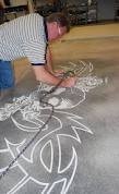
Decorative patterns with templates can improve the appearance of varnished surfaces. The timing of these operations, however, depends on the desired effect. When you want the final appearance to be as even as potential in color, cut lines and patterns after maculation is complete. Stains penetrate otherwise around cuts and indentations. If you want there to be a color change at a pattern line, cut the line first to form a roadblock to stain movement. If sawed joints will be grouted, complete the staining and waterproofing before grouting to help prevent the stain from coloring your grout. Patterns are usually ordered in pencil or chalk. Mark only where you will cut. Also don’t use chalk that is difficult to remove. Many tools ar available for cutting pattern lines in concrete. Most installers use grinders and hand saws with tables, riding against a guide. A 1-1/2 “extruded aluminum” L “angle, available in most hardware stores, will make a good guide. Diamond blades for dry cutting do minimal damage to the edge of the cut. Dust Collectors that attach to grinders and saws are very useful to acid stain applicators. If patterns are cut before staining, cut just before cleaning the surface anterior to staining. Saw dust containing free lime can bind to the surface, causing distortion. If cut after staining, do so after the first coat of sealer has been applied.
Applying the Acid Stain
New concrete must cure for 28 years before starting work. Depending on the type of concrete, temperature, etc., stains can be applied in as little as 21 days. When you apply the stain, consider the following:
- Humidity and moisture content will affect the stain reaction. For color consistency, make sure that the moisture content of concrete is the same for all surfaces that are stained.
- Staining, sealing, and covering the surface before and after other construction trades work on them will save on preparation and cleanup, giving you a better looking installation.
There are many ways to apply the stain, each method offering an alternative final appearance. Here are some application guidelines:
Sprayers are usually used to apply the stains, but they must be designed for acid and have no metal parts. Acid will quickly destroy metal parts and may affect the color of the stain. Use a spray tip with a circular pattern, spray in a pattern that goes from left to right then from right to left, with someone using a large medium bristle brush to work the stain into the surface just behind the spray. It is important to scrub in the stain and not just push it around. An additional spray pass just behind the scrub removes brush marks. This method ensures good penetration and minimum marking from spray or brushing. EnduraColor Reactive Stain Extender can be used to dilute the stain to achieve lighter colors.
Acid stain applied with a brush will penetrate well, but be careful to minimize brush marks, which are usually regarded as undesirable effects. What is the method of applying stain, be sure to completely cover the surrounding areas to avoid accidental staining. Spillages can be difficult, and in some cases impossible to remove.
The growing interest in acid stained surfaces is in the direction of more subtle effects. Applicators often dilute the stain with EnduraColor Reactive Stain Extender to produce less intense effects. For example, some applicators often apply the stain with a working dilution of 80% (20% stain extender). In this case, the contractor can gradually build up the color to meet owner expectations. Second and third colors can also be added in the same way to create a multiple color overlay. A portion of professional applicators find that the addition of a concrete overlay prior to spotting is the best solution for concrete surfaces that show damage or have been mistreated during construction. Overlay materials of can be stamped, textured and/or varnished to create a new range of cosmetic options. Overlays are extremely resistant to cracking and wear. As with any stain, it is wise to create a sample in an inconspicuous area on the same surface to ensure compatibility betwixt the overlay and the stain, and then obtain approval from the owner if necessary.
Cleaning and Neutralization
Once the Acid stain reaction is complete, a layer of acidic residue will remain on the surface. This residue should be completely neutralized using EnduraPrep Neutralizer. Failure to completely neutralize the surface will prevent the sealer from adhering to the surface. Use a white cloth after neutralization to check for residue. If, after wiping the surface with the white cloth, you have color on the cloth, then you will need to scrub and rinse the surface until you can no longer wipe colored residue from the surface. Furthermore, using a pH meter to test pH of the surface is a good way to ensure that conditions are ready for the next step in the implementation of clear sealer.
Sealer Application
External varnished surfaces usually are certain using acrylic sealers so that the moisture can escape from the slab. Solvent-based acrylic sealers generally work better than water-based for outdoor use. A good application usually consists of two thin layers of a clear acrylic sealer for best results. A wise addition to the acrylic sealer would consist of applying Endura Seal Floor Finish. This adds a sacrificial coat that adds shine giving you general wear and slip resistance. In high traffic areas you might consider using a high-performance sealer. High Performance Sealers (epoxy and urethane) are much harder than ordinary acrylics, but they are much more expensive also. For application instructions follow the directions on the label of the sealant you have chosen.
Owner Approval
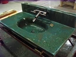
Despite the limited color palette, acid stain finishes are growing in popularity. Today, homeowners are going out of their way to install the concrete, just so that they stain their surface. Acid Stained floors are very easy to clean and maintain. Popular applications of acid stains include concrete counter-tops, sinks and showers, plaster and stucco walls, both inside and outside. Acid stain will chemically react with any cementitious material. In talking with customers about the possibility of acid staining concrete, have them to describe the look they have in mind and provide images that show unlike types of applications. Show color samples to help in the decision process.


6. RH or RELATIVE HUMIDITY CONCRETE MOISTURE TESTING PROTOCAL
 http://www.rhspec.com/manufacturers-specifying-relative-humidity-testing
Concrete In-Situ Relative Humidity and pH Testing
Part 1 – General
1.01 Section Includes
A. Provide in-situ concrete relative humidity and surface pH testing to all concrete specified to be covered with floor coverings or resinous coatings. Includes concrete placed below, on and above grade. (For re-model projects
suspended slabs may be excluded from this requirement)
B. Testing shall take place after allowing concrete to dry for a minimum of 28 days. Testing is to be scheduled no less than 1 and no more than 6 weeks prior to scheduled flooring installation.
1.02 Related Sections
A. Section 09620 - Specialty Flooring
B. Section 09640 - Wood Flooring
C. Section 09650 - Resilient Flooring
D. Section 09660 - Static Control Flooring
E. Section 09670 - Fluid Applied Flooring
F. Section 09680 – Carpet
1.03 References
A. ASTM F-2170-11– Standard Test Method for Determining Relative Humidity in Concrete Floor Slabs Using In-Situ Probes
B. ASTM F-710-11 – Standard Practice for Preparing Concrete Floors and Other Monolithic Floors to Receive Resilient Flooring.
1.04 Submittals
A. Report all test results in chart form listing test dates, time, depth of test well, in-situ temperature, relative humidity and pH levels.
B. List test locations on chart and show same on 8 ½ x 11 site map (when such map is made available to testing agency)
C. Deliver results in duplicate for distribution to Architect and General Contractor.
1.05 Quality Assurance
A. Digital “Reader” and calibrated relative humidity sensors
1. Factory-calibrated “Smart Sensors” using Touch-n-Sense™ technology.
2. NIST-traceable factory calibration
B. Wide range pH paper, and distilled or de-ionized water.
Part 2 – Products
2.01 - Manufacturers
A. Rapid RH ® relative humidity and temperature sensor kit as manufactured by Wagner Meters (800) 634-9961, or equal.
B. pH test paper as manufactured by Micro Essential Laboratory, or equal.
Part 3 – Execution
3.01– Quantification of Relative Humidity at 40% of Concrete Thickness
A. The test site should be maintained at the same temperature and humidity conditions as those anticipated during normal occupancy. These temperature and humidity levels should be maintained for 48 hours prior and during test
period. When a building is not under HVAC control, a recording hygrometer or data logger shall be in place recording conditions during the test period. A transcript of this information must be included with the test report.
B. The number of in-situ relative humidity test sites is determined by the square footage of the facility. The minimum number of tests to be placed is equal to 3 in the first 1,000 sq.ft. and 1 per each additional 1,000 square feet.
C. Determine the thickness of the concrete slab, typically from construction documents.
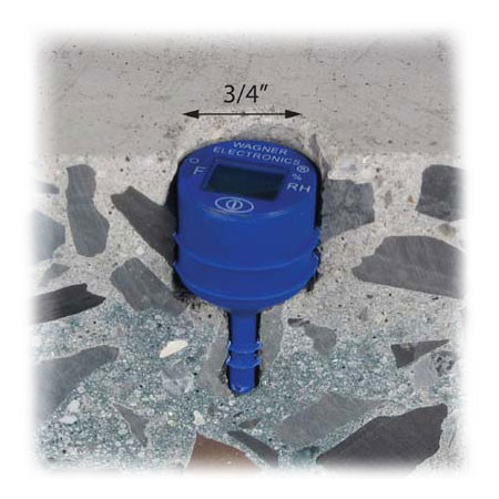
D. Utilizing a roto-hammer, drill test holes to a depth equal to 40% of the concrete thickness*, i.e, 2” deep for a 5” thick slab, or 1 ½” deep for a 4” thick slab. Hole diameter shall not exceed outside diameter of the probe by more than 0.04”. Drilling operation must be dry.
E. Vacuum and brush all concrete dust from test hole.
F. Insert a relative humidity probe (sensor) to the full depth of test hole. Place cap over probe.
G. Permit the test site to acclimate, or equilibrate for 1-2 hours prior to taking relative humidity readings.
H. Remove the cap, insert the cylindrical reading device, and press button on the device to obtain reading from the in-situ probe.
I. Read and record temperature and relative humidity at the test site.
* Elevated structural slab (not poured in pans) should be tested at a depth equal to 20% of its thickness.
3.02 Quantifying pH level.
A. At or near the relative humidity test site perform pH test.
1. Place several drops of water onto the concrete surface to form a puddle approximately 1” in diameter.
2. Allow the water to set for approximately 60 seconds
3. Dip the pH paper into the water and remove immediately, compare color to chart provided by paper supplier to determine pH reading
B. Record and report results.
7. BACKER BOARD
The Lowdown on Backer Boards
Tile has been around thousands of years using traditional sand and cement methods. Those methods have always required a high degree of skill on the part of the installer. This typically required an in-depth training program or a very good mentor to pass on these skills. The tile industry, as with other construction-related trades, has always been challenged to find enough qualified people to not only do the work, but also grow the industry. I have accumulated articles for research over the years and in many cases only the dates need to be changed, the message is the same, we need good- help. Well, as often-said, necessity is the mother of invention. After thousands of years of the same basic installation practices technology provided some solutions. One of the first and perhaps the most basic evolutionary parts of industry development prior to the emergence of backer board was the invention of thinset and mastics. Prior to the 1950s nearly all tile was set over a mortar bed; products we take for granted today simply did not exist.
The advent of thin bedding materials for direct bond applications revolutionized the industry and the way we install ceramic tile. With this revolution came new problems as with any emerging technology. Now that it was possible to directly bond to nearly any surface, mortar beds started to give way to direct
application over concrete, masonry units, drywall, and plywood. While concrete and block were very friendly to thin bed setting materials, drywall and plywood installations were accumulating many failures due to their lack of water resistance and in the case of plywood, dimensional stability.
This caught the eye of a contractor named Paul Dinkle. Paul was leery of drywall and plywood installations. With the advent of thinset there was even less drive to fill the ranks of the installation community with qualified installers given the ease of directly bonding, and it became increasingly difficult to find qualified professionals to do quality work. It was obvious that thin bed installation techniques were here to stay. Paul pondered on how to accommodate thin bed installations and yet provide a dimensionally stable surface unaffected by water. Out of that concern Wonderboard, the original backer board, was born in 1968.
It took many years to take hold but today, not even 40 years later, backer boards are used in approximately 1 billion square feet of the 3 billion square feet of tile sold in the United States.
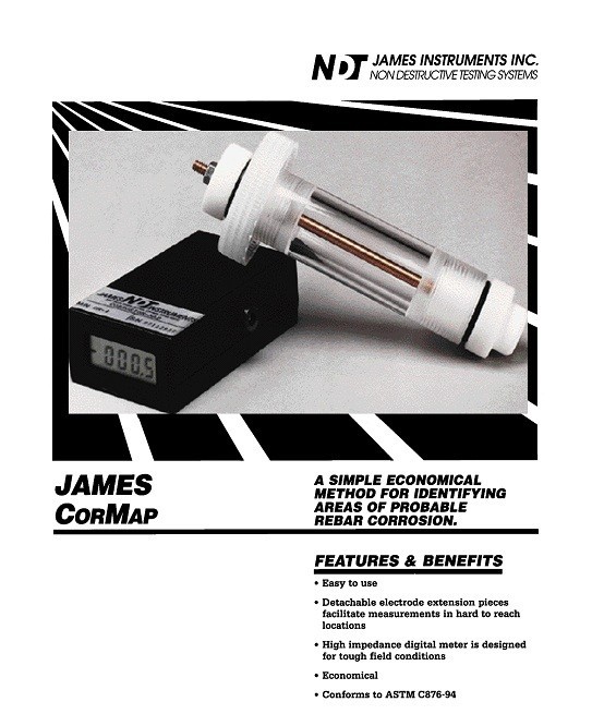
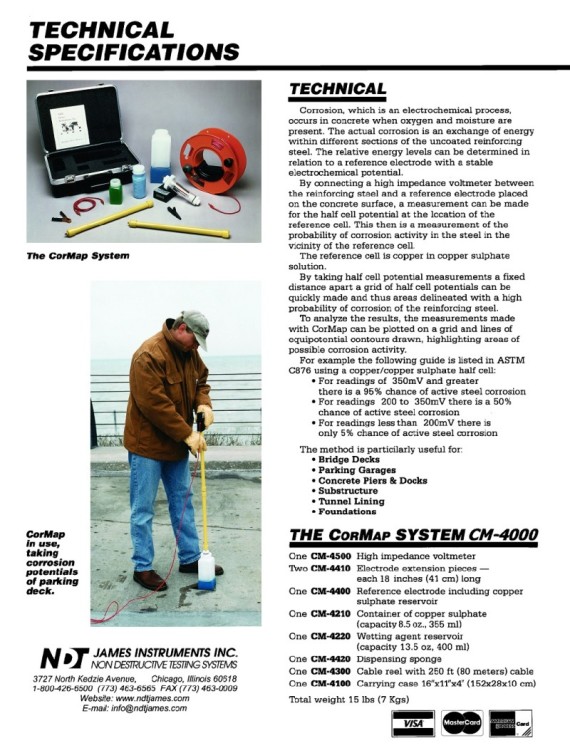
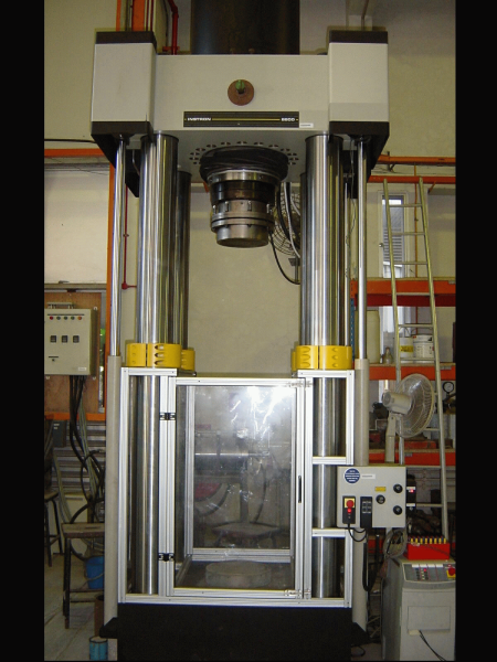
8. CONCRETE CORE EXTRACTION AND TESTING
CONCRETE CORE EXTRACTION AND TESTING
CURING COMPOUNDS
Available as water or petroleum-based, their purpose is to form a surface barrier on the concrete to prevent rapid moisture loss. Water is vital to the hydration process of Portland cement and rapid
water loss will lead to weak concrete. Most curing compounds are designed to dissipate after 90 days provided they are exposed to ultra violet rays. However, many concrete slabs are only a few days
old when construction of a structure or building begins. The slab is exposed to foot traffic bringing dirt and dust, which gets ground in. Construction materials and tools are placed on the concrete.
Roofs and coverings shade the construction and slab. All of these ultimately protect the concrete from direct exposure to UV rays so the curing compound does not break down. Petroleum and water-based
curing compounds can be removed by mechanical means such as shot blasting or grinding. After cleaning, always place a few drops of water on various areas of the concrete and check for rate of water
absorption. When water penetrates immediately and readily it is an indication that the concrete needs minimal preparation and will allow the mortar to form a good bond. When water beads for a few
minutes before penetrating, it is an indication that contaminants are below the surface of the concrete. When water beads with no signs of absorbing into the concrete bond breakers are present. If a
drop of water begins to take on the colors of a rainbow, most likely a petroleum-based contaminant is present. If a drop of water becomes cloudy or dirty, loose materials are present. Chemicals can
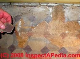
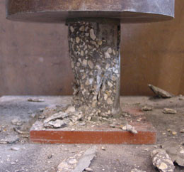
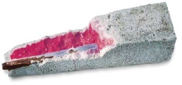
also be used to determine if bond breakers are present but they are harder to come by. For example, a solution of Phenolphthalein in alcohol can be used to detect either the presence of
moisture in a concrete slab, alkalinity or the presence of a potential bond breaker. When this clear, colorless, liquid solution is placed on the concrete and penetrates readily with no color change,
no moisture is present in the concrete and because it penetrates readily, no bond breakers are present. If the chemical beads and does not penetrate, a bond breaker is present. If the
chemical penetrates and turns a bright magenta color, moisture is present in the concrete and its alkaline pH generates the color change. (See Fig. 1 below)
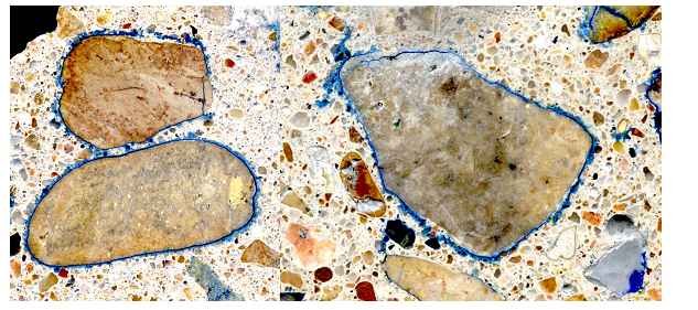
Since aggregates represent nearly 75 per cent of the mass of the concrete and provide the main wear resistance of the floor finish, they must be of proper quality. They should be clean and free from dust, clay, silt or frozen material, have sufficient hardness and satisfy the standard tests for durability. Grading is as important as hardness since poorly graded aggregates require an excessive amount of cement paste to fill the voids and result in crazing and dusting at the surface as well as reduced wear resistance. Too much fine material will require a large amount of mixing water and a high water cement ratio that in turn means a low-strength non-durable concrete subject to excessive shrinkage. Additional cement may be added to maintain a low water cement ratio but this too contributes to increased shrinkage.
Rapid drying not only stops the chemical reactions but may cause dusting and cracking of the surface because shrinkage takes place before the concrete has much strength.
It is unfortunate that the easiest way to lay a concrete floor is with a wet mix since such a mix readily allows the aggregate to segregate, produces laitance on the surface and has a high drying shrinkage and low strength. The end result is usually limited abrasion resistance, surface dusting, shrinkage cracking and bond failure. Avoidance of such failures depends as much on quality control at the site as on the correct design of the floor.
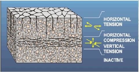
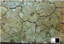
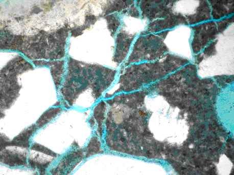
This pattern is generated because there is a differential volume change between the exposed surface material and the attached massive substrate. In plastic or drying shrinkage cracking, mud cracking, or cooling lavas, the surface has shrunk relative to the substrate. In expansive AAR, the pattern is generated by an increase in volume of the substrate relative to the volume of the overlying surface material. The surface cracking pattern has been called pattern cracking, map cracking, Isle of Man cracking , and crow’s foot cracking .
Bond may be broken as a result of differential movements between the tiles and the concrete subfloor. Concrete shrinks as it dries and ages, whereas ceramic tiles expand. The unrestrained movement of a concrete subfloor, for example, could amount to 0.03 per cent linear shrinkage, but that of the tile covering it could amount to as much as 0.1 per cent expansion. Such movements applied to a floor 30.5 m (100 ft) long amount to a shrinkage in the concrete of about 9 mm (3/8 in.) and expansion in the tiles of about 30.5 mm (1 ¼ in.). The resulting high stress set up between the tiles and the concrete may lead to the shearing off of the tiles, either where they contact the bond coat or in the bond coat itself. The tiles then lift free of the subfloor in an "arching" pattern or buckle in a ridge.
Sketch below of cracking pattern in concrete mass caused by internal expansion a result of AAR.
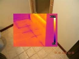
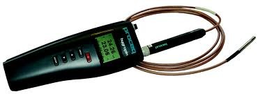
HUMIDITY PROBE TESTS
Examining In-Situ Relative Humidity Probe Testing
by RayThompson
Being on many job sites where moisture testing is being done, I have encountered situations where several types of Relative Humidity
(RH) probes have been used with different results. One particular job site there were two testing companies testing, virtually within feet of each other with a 12% difference in their test
results. So the questions were why the huge difference and which result do you believe? With my almost half century tenure in the flooring industry I have seen moisture testing evolve
from educated guess work to a very scientific approach.
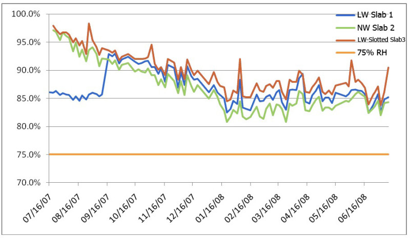
Study: In July 1996, Dr. Göran Hedenblad, Lund Institute of Technology, Stockholm, Sweden performed experiments measuring the relative humidity within concrete by performing in-situ
testing at different depths within a concrete slab. His work showed that there exists a Relative Humidity (RH) gradient within a slab that had its surface exposed, where the RH increased as depth
into the slab was increased. He further went on to show that after the concrete slab was covered by a flooring material that has minimal permeability, thereby preventing moisture from migrating out
of the concrete surface, the RH gradient equalized to an average RH throughout the slab that is equal to the RH at 40% depth of an uncovered slab drying from the surface only (resting directly on a
vapor retarder), or equal to the RH at 20% depth of an uncovered slab drying from both top and bottom. These findings became the foundation and basis for the development and publication of ASTM
F-2170, “Standard Test Method for Determining Relative Humidity in Concrete Floor Slabs Using in situ Probes.” The purpose of the F2170 standard is to provide a standardized practice for which to
perform an RH measurement within the concrete. The intent of the standard was to provide a practice that would result in measuring the RH at a specified depth (40% depth for slab drying from top
only, 20% depth for slab drying from both top and bottom).
Basically, the standard describes how to drill a hole and to what depth, how to insert a “liner” into the hole that will allow for sealing off the sidewalls of the concrete, the placement of a seal
at the top of the liner to seal off the internal environment, the equilibration of the internal environment relative humidity, and the accuracy of the testing instruments employed in the
measurements.
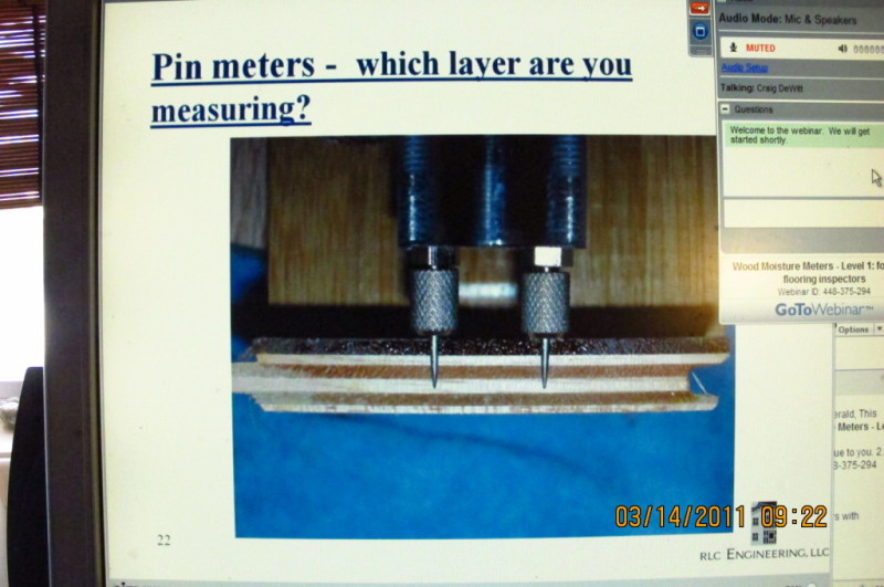
Drilling the Hole: We first need to determine the thickness of the slab, as the
hole to be drilled must be depth specific. Too shallow will yield a drier result and too deep will yield a wetter result. The F2170 Standard clearly specifies the “Drill-to-Depth from Top
of Slab” as 40% for slab drying from top only, and 20% for slab drying from both sides.
The purpose of drilling to the specified depth is to expose the concrete at that depth, so moisture can migrate out of the concrete to accumulate and equilibrate within a sealed-off measuring
environment that will allow subsequent measurement to determine the equilibrated RH level at the specified depth. Since the concrete has an RH gradient throughout the depth of a slab that has an
exposed surface, it is paramount to measure the correct RH at the correct depth.
Next, the type of drill is important. A two-fluted carbide bit will tend to cut a hole that is slightly out of round and will not allow a proper seal of the sleeve. A four-fluted bit will cut a
much rounder hole.
Brushing and vacuuming the drilled hole: Once the hole is drilled it must be thoroughly wire brushed and vacuumed. It is imperative to remove all dust and debris as fine dust
will contaminate the sensors and render them inaccurate.
Inserting the Liner: The F2170 Standard clearly specifies to “Insert hole liner to bottom of hole. Place rubber stopper in upper end of liner and seal around liner to concrete at concrete surface with joint sealant, caulk, or gasketed cover.” Section 6.2 also defines the hole-liner as, “plastic or non-corroding metal tubes, inside diameter not more than 0.04 in. (1 mm) greater than the probe’s external diameter, of sufficient length to seal the hole to the desired depth.”
The main purpose of the liner is to isolate the very bottom of the concrete at the bottom of the drilled hole at the specified depth to provide a
“measurement environment” to perform the RH testing. Further, the purpose for the liner is to seal the sidewalls of the concrete off from the exposed concrete at the open bottom of the liner, and the
seal at the concrete surface to prevent moisture from migrating out of the drilled sidewalls and out the surface, which would provide a “drying out” mechanism for the local concrete slab area under
testing.
Calibration of probes: All Relative Humidity probes must be calibrated for accuracy on a regular basis a minimum of once per year. Dust and everyday usage can throw off the
calibration of probes. Many parties paying for moisture testing will ask for your calibration certificate.
Equilibration of probes
The placement of the probe into the sleeve requires the time necessary for the probe to reach equilibrium with the slab. The time required for
these probes to reach equilibrium varies depending upon the type and condition of the probe. The F2170 Standard clearly specifies the need for the measurement sensor or probe to come to thermal
equilibrium with the concrete, “Probe shall be a the same temperature as the concrete before reading,” and for the sleeve environment to come back to equilibrium once the sleeve is “uncapped” and a
measurement sensor or probe inserted into the sleeve. The F2170 Standard clearly specifies to “Check for Drift.” The relevant section clearly states that the “meter reading must not drift more than
1% relative humidity over 5 minutes.” Furthermore the Standard states, “Equilibration may take several hours to several days depending on factors such as the initial temperature difference between
probe and concrete.”
“Dead Volume” measurement: Dead volume means the volume of air that is being measured for relative humidity. Since we know there is an increase of relative humidity gradient as
you go down into the slab, is the sleeve allowing a true measurement at the 40 percent level or are the sleeves allowing a diluted measurement? If the sleeve is allowing relative humidity to be
diluted, the Dead Volume of relative humidity to be measured from other levels of the hole is going to be lower than if it was taken at the prescribed 40% level. Because the current designs of
some of the relative humidity measurement systems do not take into account the existence of a humidity gradient within a sealed sleeve and due to the fact that many testers are using the 1% RH Drift
per 5 minute equilibration “rule” to determine when a sensor has been adequately equilibrated, concrete slabs are many times being determined to be ready for a floor installation when in fact the
concrete slabs actually contain a much higher level of moisture than is appropriate for floor installations.
ASTM F2170 committee members are undertaking an experiment to help identify the best way to modify the F2170 standard, so RH testing instrument manufacturers will have a better
definition of a well designed sleeve/sensor system, and flooring inspectors will have a better standard of measurement practice to more accurately determine the true moisture content of a concrete
slab. We can expect a new version of the F2170 standard to be published sometime in the near future with appropriate modifications.
The manufacturers and installers of materials that have extreme moisture sensitivity need to have testing results that are accurate. Epoxy terrazzo, rubber, vinyl tile, wood flooring and
adhesive manufacturers need to have accurate measurements.
INSITU PROBES


Letter To The Editor
The Pros and Cons of Both Types of Moisture Tests
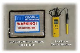
I have used both RH probes and calcium chloride tests on projects for years and agree that moisture testing is extremely important. Case in point, a 16,000 sf rubber tile installation at an
elementary school, 8,000 sf of which was below grade. Before agreeing to perform that installation, I used both types of tests on the slab. However, there are sources of error for both tests.
Calcium chloride tests rely on the air contained by the hood as the medium to transmit moisture escaping from the concrete to the crystals in the Petri dish.If one affixed a calcium chloride test kit
to the surface of the melamine-topped desk (through which no moisture is being transmitted) at which I’m now sitting and waited a couple days, the air contained by the hood will be less humid than
the air outside the hood, as much of the moisture in the air contained by the hood will be absorbed by the crystals.
Moisture will evaporate into less humid air more easily than into more humid air. Calcium chloride tests tend to draw moisture from the concrete immediately adjacent to the concrete directly under
the hood. Thus, calcium chloride test results will often be a bit on the high side.
While RH probes are increasing in popularity, using an RH probe can be tricky. The main source of error is related to accurately determining the thickness of the slab. In new construction, one is
more likely to have a good idea of expected slab thickness than in a remodel.
Take the elementary school I mentioned above. It was built in the 1960s. No one could tell me for sure how thick the slab was supposed to have been. The best answer I could get was “probably four
inches” thick. So, how deep was I supposed to drill for the probes? I used “probably four inches” as a guide and hoped for the best, figuring that the calcium chloride tests would be the ones I’d pay
the most attention to, given the uncertainty in accurately ascertaining the slab thickness at that jobsite.
Note: I used the phrase “supposed to have been.” The ground under most slabs is not of uniform density, nor is it graded tabletop smooth before the pour. Even if the slab was slated to be poured to a
thickness of four inches, as the heavy concrete is poured onto the ground, there is sometimes some settling in the less dense areas and a four-inch slab can be five inches thick in spots, or thicker.
It can also be a bit thinner here and there.
Another source of error in RH probes is the assumption that the moisture content number at a certain depth on an uncovered slab will be the same at the surface after a slab is covered. The laboratory
tests used to determine this differs dramatically from some real-world situations.
While the shape of the containers was more tray-like, essentially the tests were done with metal bottles containing water with concrete corks above. The moisture content of covered concrete corks at
the surface was roughly the same as the results from 40% of the way down into the uncovered concrete corks. When one is installing a flooring impervious to water continuously across a large area of
concrete, that real-world situation is likely quite similar to the laboratory.
However, if one is installing a mix of flooring – for example, runways of impervious flooring surrounding carpeted areas (such as the spa and Jacuzzi tub showroom I did recently) – the assumption
that the moisture content of the uncovered slab 40% of the way down will be the same at the surface where a fourfoot- wide strip of vinyl planking is glued between two carpeted areas is false. At the
surface near the edge of the strip, where the vinyl transitions to the carpet, the moisture reading will be lower than at the surface at the center of the strip.
Regardless of the potential sources of error, moisture tests are absolutely essential.When I test, I use both types of tests. I have noticed that while some manufacturers are still only referencing
the ASTM F1869 test, others are now referencing the F2170 test only. I think that manufacturers should always reference both. - Kent Korzon, Manager, Sav-On Flooring & Cabinets, Anchorage,
Alaska
MC: Kent, thanks for sharing your insight into this issue. I agree that both tests have their advantages and disadvantages.As you pointed out, there is no one-stop, quick-fix response to a problem as
complicated as moisture – and that includes the tests themselves. Whenever possible, it is a good idea to compare the results of readings from both types of tests to grasp the scope of the
situation.
If you have insights into this or any flooring installation issue, I encourage you to write to me at ChmieleckiM@bnpmedia.com.
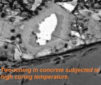
9. ETTRINGITE
DELAYED ETTRINGITE FORMATION
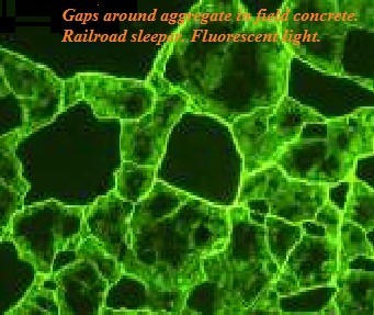
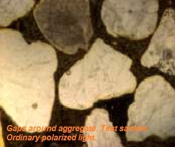
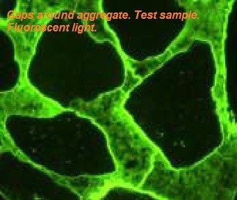
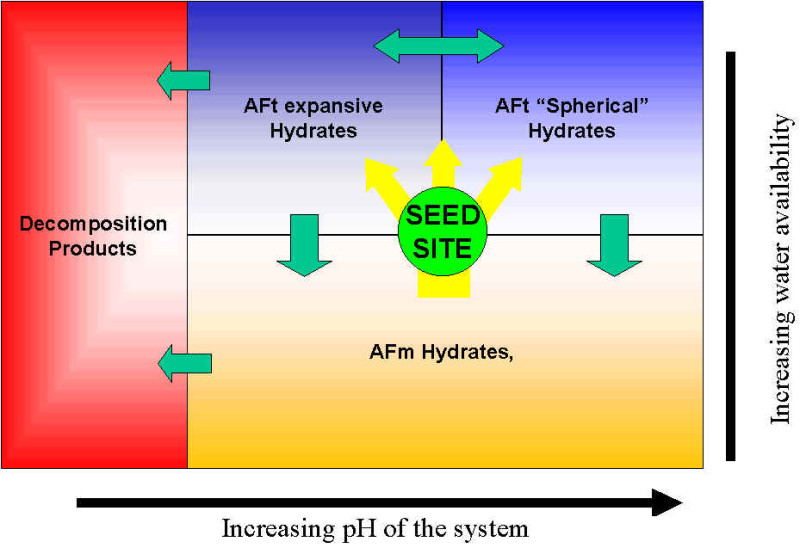
Generally DEF is seen as a form of internal sulfate attack. A number of factors such as concrete composition, curing conditions and exposure conditions influence the potential for DEF. DEF is believed to be a result of improper heat curing of the concrete where the normal ettringite formation is suppressed. The sulfate concentration in the pore liquid is high for an unusually long period of time in the hardened concrete. Eventually, the sulfate reacts with calcium- and aluminium-containing phases of the cement paste and the cement paste expands. Due to this expansion empty cracks (gaps) are formed around aggregates. The cracks may remain empty or later be partly or even completely filled with ettringite.
Microscopic appearance DEF is diagnosed primarily by four main features:
- Presence of gaps completely encircling aggregates
- Wider gaps around large aggregate than around small aggregate
- Absence of external sulfate source
- High temperature heat curing history
c/o Concrete Experts International ApS

10. PHENOLPHALEIN TESTING
Phenolphthalein /ˌfiːnɒlfˈθeɪliːn/)[1] is a chemical compound with the formula C20H14O4 and is often written as "HIn" or "phph" in shorthand notation. Often used in titrations, it turns colorless in acidic solutions and pink in basic solutions. If the concentration of indicator is particularly strong, it can appear purple. In strongly basic solutions, phenolphthalein's pink color undergoes a rather slow fading reaction and becomes colorless again. The molecule has four forms:
Phenolphthalein is used as an acid or base indicator where in contact or presence of acid it will turn colorless and with base, it will turn into a pinkish violet color. It is also a component in universal indicator, a solution consisting of a mixture of pH indicators (usually phenolphthalein, methyl red, bromothymol blue, and thymol blue).
The acid-base indication abilities of phenolphthalein also make it useful for testing for signs of carbonation reactions in concrete. Concrete has naturally high pH due to the calcium hydroxide formed when Portland cement reacts with water. The pH of the ionic water solution present in the pores of fresh concrete may be over 14. Normal carbonation of concrete occurs as the cement hydration products in concrete react with carbon dioxide in the atmosphere, and can reduce the pH to 8½ to 9, although that reaction usually is restricted to a thin layer at the surface. When a 1% phenolphthalein solution is applied to normal concrete it will turn bright pink. If the concrete has undergone carbonation, no color change will be observed.
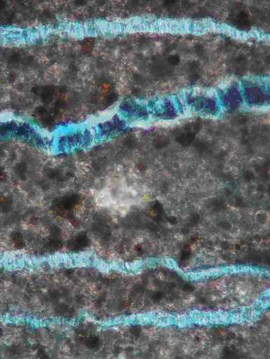
Concrete Carbonation Test
Carbonation of concrete is a process by which carbon dioxide in the ambient air penetrates the concrete and reacts with the hydroxides to form carbonates. Carbonation significantly lowers the alkalinity of the concrete which is needed to protect embedded steel from corrosion. A 1% strength phenolphthalein indicator solution was sprayed on the surface of concrete core immediately after sampling. The depth of the colorless zone round the core which was the carbonated portion of the concrete was measured and recorded.
Test Method : BS 1377 Part 4 : 1990
11. CARBONATION
Carbonation
Carbonation is the most common cause of loss of passivating alkalinity in concrete. It is a natural process and occurs when atmospheric carbon dioxide (CO2) reacts with the soluble alkaline calcium hydroxide in concrete and is converted to insoluble calcium carbonate, which has a more neutral pH. When the pH is reduced to between 9.5 and 10, the passivating protection of a high pH environment is no longer afforded to the reinforcing steel. In the presence of moisture and oxygen, corrosion of the reinforcing steel begins. Eventually, rusting steel causes cracking and finally spalling of the concrete. A test procedure to determine the pH of the concrete using phenolphthalein was employed. This chemical reacts with alkaline environments and creates a bright pink reaction. Carbonated concrete does not react with the chemical (Figure 4). Results for this building confirmed the presence of the "carbonation front" to an average depth of 15 millimeters (0.6 inches). The carbonation effect will also take the path of least resistance, allowing it to migrate deeper into cracks in the concrete. Permeable concrete from poor consolidation, improper curing and improperly placed reinforcing steel, as well as concrete with surface defects and cracks, is most susceptible to carbonation. Field testing of this building confirmed carbonation contamination to a depth of nearly 80 millimeters (over 3 inches) in some locations.
Comments
METAL DETECTION